Getting started
Getting Started
Introduction
What is Audulus?
Audulus is a modular synthesizer and visual programming environment for iOS, iPadOS, and macOS. Whether you're composing music, designing sound for film, crafting unique synthesizer patches, or experimenting with audio algorithms, Audulus gives you the tools to build exactly what you need.
From beginners taking their first steps into synthesis to experts designing complex instruments, Audulus adapts to your level. Its node-based interface makes signal flow visible and tangible, turning abstract audio concepts into something you can see, touch, and rewire.
The Power of Modular Synthesis
The modular synth movement sparked a wave of innovation and exploration in audio synthesis. The Eurorack world is filled with esoteric, bespoke, and idiosyncratic creations, all driven by a spirit of discovery. Audulus embraces this same spirit—we love the modular audio world, but as a digital platform, we also draw from the rich history of computer music and experimental signal processing.
In traditional synthesizers, the signal path is fixed:
Oscillator → Filter → Amplifier
You get what the designer gave you. No more, no less.
Modular synthesis breaks these constraints wide open. Every module—oscillator, filter, envelope, sequencer—becomes a building block you can connect however you want:
Oscillator → Amplifier → FilterLFO → Filter → Delay → FilterSequencer → Oscillator → Oscillator → Filter
Want to use an envelope to control delay time? Connect them. Want to feed a filter's output back into its own input? Do it. The patch cables become the architecture of your sound.
This freedom transforms synthesis from operating an instrument into designing one. In Audulus, you're not just making music—you're building the instruments that make it.
Visual Programming in Audulus
Audulus uses "nodes" - small blocks of code that you connect with virtual patch cables. By linking nodes together, you create programs that Audulus compiles and runs in real time.
Device Compatibility
Standalone App: Audulus runs on iPadOS, macOS, and iOS—compatible with all Apple devices. Performance varies based on your device's specifications, as Audulus leverages modern Apple technology that may be more demanding on older hardware.
Plugin: Audulus includes an AUv3 plugin that works with any compatible DAW or host application.
Cross-Device Workflow: Audulus patches sync seamlessly across your devices via iCloud. The audio engine remains identical across all platforms—only performance and interface layout differ. A patch will run faster on a newer iPad Pro than on an iPhone, but the sound and functionality stay the same.
Core Concepts
The Patchbay
The patchbay is Audulus' infinite workspace where you build patches. It dynamically adapts to your patch size. You'll run out of computing power before you run out of space.
Signals
Signals are streams of numbers flowing between nodes at your audio sample rate. There are two types:
Audio Signals
- The sound you hear from speakers or headphones
- Should stay between -1 and 1 to avoid clipping/distortion
Control Signals
- Modify parameters like volume, filter cutoff, etc.
- Operate in the 0 to 1 range for compatibility
Signal Flow
- Signals flow left to right, from outputs to inputs
- One output can connect to multiple inputs
- One input can only receive from one output
- To combine multiple signals, use math nodes (Add, Multiply) or mixer modules
CPU Monitoring
The CPU:% display (bottom right) shows your patch's processor usage. Use Timing mode to see which nodes/modules use the most CPU. High CPU may make your audio sound slower and cause dropouts (crackling, artifacts).
Audulus has a setting to use multi-core processing. Turn this on for best performance.
However, using Timing mode with multi-core can switch to high CPU use - use it with caution.
User Interface Guide
iOS (iPhone & iPad)
First Launch Setup
- Grant microphone permission when prompted
- You'll see the Patch Browser
Patch Browser
Navigation:
- Drag up/down to browse
- Pull down for Search Bar
- Pull up for Date/Name sorting
- Pull up further for tag filters
Patch Management:
- Open: Tap patch screenshot
- New: Tap + icon (top left)
- Rename: Tap patch title
- Duplicate/Delete: Tap "Edit", select patch, tap icon
Patches auto-save when you exit.
Patchbay Controls
Navigation:
- Pan: Two-finger drag
- Zoom: Pinch gesture
- Zoom to fit: Tap patchbay → Fit
Editing:
- Create nodes: Tap patchbay → Create
- Select: Tap blank space on node
- Lasso select: Tap patchbay, drag around objects
Connecting Nodes:
- Tap blue output
- Drag wire to red input (it grows when ready)
- Release to connect
- To disconnect: Tap input, swipe wire away
Module Browser
- Open: Tap patchbay → Create
- Close: Tap Cancel or select item
- Filter: Tap tags in red bar
- Browse: Nodes first, then modules
On-Screen Keyboard
- Show: Tap chevron (bottom left)
- Octave: Tap up/down arrows (range: -3 to 3)
- Middle octave: 0 (A=440Hz)
Performance Mode
Tap the padlock icon to lock nodes in place. You can still interact with controls, zoom, and pan without moving objects.
Node/Module Functions
Tap any blank space on a node or module:
- Cut/Copy/Paste
- Delete
- Group (create Subpatch)
- Help (requires internet)
Module-Specific:
- Open (view contents)
- Edit UI / Lock UI
- Add to Module Browser
Desktop (macOS)
Getting Started
Launch Audulus to see the file browser. Patches use the ".audulus" extension.
Example Patches: File → Open Example
Patch Management
- New: File → New (⌘N)
- Open: File browser, File menu, or double-click
- Save: File → Save (⌘S)
- Rename: Click chevron next to patch name
- Duplicate: File → Duplicate (⇧⌘S)
Multiple patches can be open simultaneously in tabs. Thanks to infinite undo, progress is saved even if Audulus crashes.
Patchbay Controls
Navigation:
- Pan: Alt + click and drag
- Zoom: Mouse wheel
- Zoom to fit: Double-click patchbay
Editing:
- Create nodes: Right-click patchbay
- Select: Click blank space on node
- Lasso select: Click and drag on patchbay
- Multi-select: Shift + click objects
Connecting Nodes:
- Click and hold blue output
- Drag wire to red input (it grows when ready)
- Release to connect
- To disconnect: Click input, swipe wire away
Module Browser
- Open: Right-click patchbay
- Structure: Nodes nested in categories, modules in separate submenu
Keyboard Shortcuts
| Action | Shortcut |
|---|---|
| New | ⌘N |
| Save | ⌘S |
| Duplicate | ⇧⌘S |
| Cut | ⌘X |
| Copy | ⌘C |
| Paste | ⌘V |
| Select All | ⌘A |
| Undo | ⌘Z |
| Zoom to Fit | ⌘F |
| Actual Size | ⌘0 |
| Zoom In | ⌘+ |
| Zoom Out | ⌘- |
| Inspector | ⌘; |
| Timing Mode | T |
| Exit Module | ⌘Esc |
Node/Module Functions
Right-click any blank space on a node or module:
- Cut/Copy/Paste (⌘X/C/V)
- Delete (Backspace)
- Group (create Subpatch)
- Help (requires internet)
Module-Specific:
- Open (or double-click)
- Edit UI / Lock UI
Adding Custom Modules
- Go to Audulus → Open Modules Folder
- Drop modules or patches into this folder
- Organize with nested folders
- Modules appear in right-click browser
Getting Help
Support is available through multiple channels:
- Email: support@audulus.com
- Discord: Join our Discord community for real-time help
- Forum: forum.audulus.com
Nodes
Introduction to Nodes
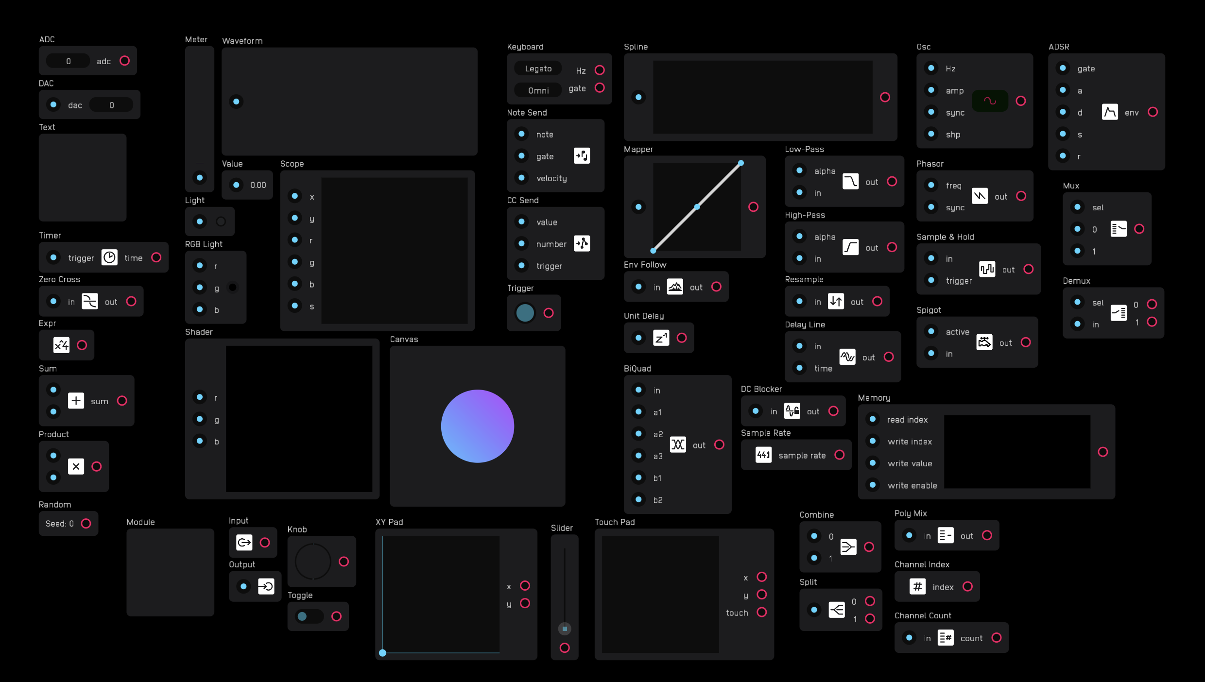
Everything in Audulus is built with nodes. There are 53 nodes in total.
Nodes are packets of code that perform specific functions. A node may have inputs, outputs, both, or neither.
Inputs are on the left side of nodes and are colored blue. Outputs are on the right side of nodes and are colored red.
Nodes can be moved around the patchbay but cannot be rotated.
Connecting Nodes
You connect nodes by dragging a wire from an output to an input. You cannot drag a wire from an input to an output. One output can connect to as many inputs as needed.
You disconnect nodes by unhooking a wire from an input. Wires cannot be disconnected from outputs. An input accepts only one wire. To connect multiple wires to one input, use an add node to combine the signals first.
Wires can go from any output to any input in any direction: up, down, left, or right. However, the overall signal flow in Audulus moves from left to right.
Signals
Nodes send and receive signals through wires. Every signal is a number. Although all signals are numbers, they fall into several categories defined by their range, unit, and usage.
Signal Types
| Signal | Range |
|---|---|
any | Any number and signal type |
audio | -1 to 1 |
gate | 0 or high (any non-zero positive 32-bit number) |
hz | 0 to sampleRate/2 |
integer | Integer values |
midi value | Integers 0 to 127 |
mod | 0 to 1 |
seconds | 0 to 2^32-1 |
Node Categories
There are 10 categories of nodes:
| Category | Description |
|---|---|
util | Various utilities |
math | Mathematical and logical operations |
meter | Signal monitoring displays |
midi | MIDI utilities |
mod | Signal level adjustment and analysis tools |
dsp | Digital signal processing tools |
synth | Essential synthesis tools |
module | Module and submodule creation |
poly | Polyphonic signal management |
switch | Signal routing tools |
Some nodes count as outputs, such as value, light, and dac nodes. If a node is not connected to an output, it will not be evaluated.
Util Nodes
Util nodes provide essential utilities for getting audio in and out of Audulus, labeling patches, timing events, and analyzing signals.
adc
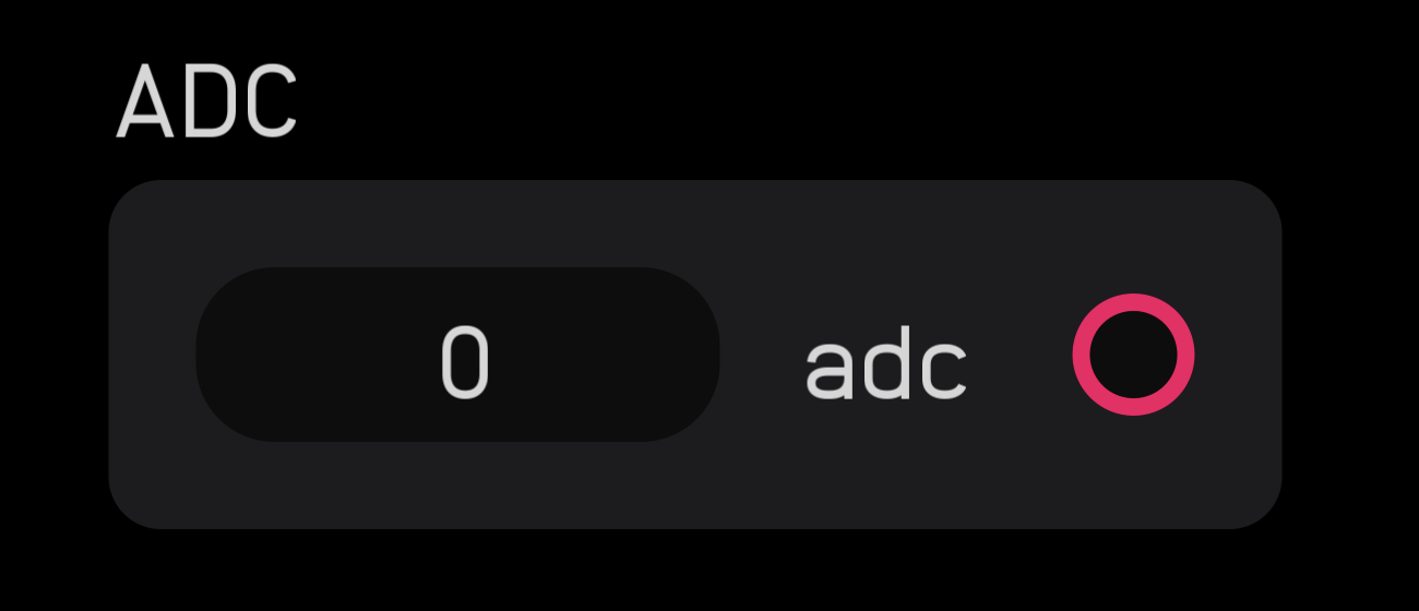
The adc node brings audio and CV into Audulus from external sources like microphones, DAWs, or hardware modular synth CV inputs.
The adc node outputs an audio signal with incoming signals clamped between -1 and 1. While often used for audio input, it can also pass gate signals from a modular synth.
The adc node can access the first 16 inputs of any class-compliant audio interface.
dac
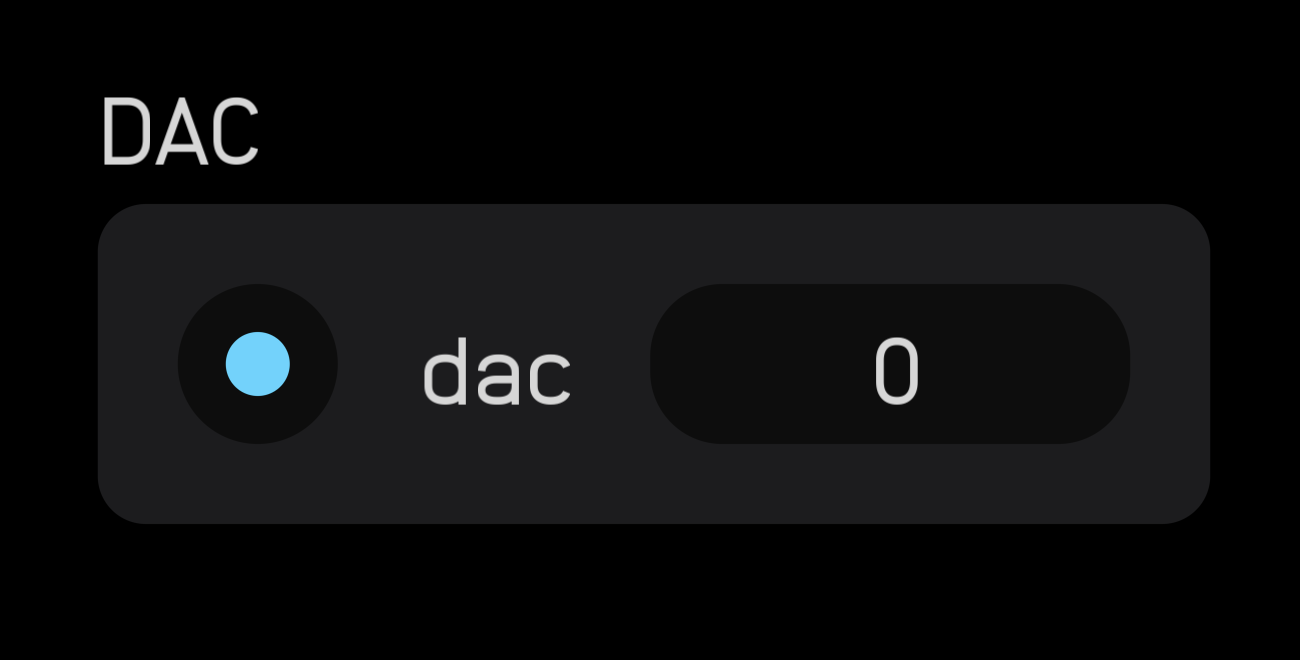
The dac node sends audio and CV out of Audulus to external outputs like headphones, speakers, DAWs, or hardware modular synth CV outputs.
The dac node accepts an audio signal input with outgoing signals clamped between -1 and 1. While often used for audio output, it can also pass gate signals to a modular synth.
The dac node can access the first 16 outputs of any class-compliant audio interface.
Best practice: Use a dc blocker node before a dac node unless you explicitly need to send a mod or gate signal to an external instrument.
text
The text node has no inputs or outputs. It's used for labeling and commenting within patches.
Click or tap the node and open the inspector panel to type in the text field. Text will appear inside the node.
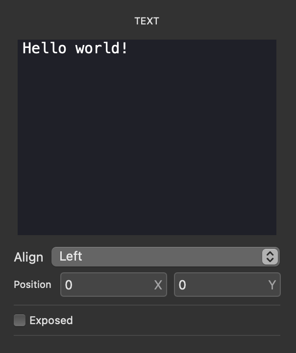
The text node text area box can be resized by tapping or clicking the blue ball that appears when selecting the node, then dragging left or right.
Available Characters
The text node supports the following characters from the Anodina-Regular font.
Standard Characters
These can be typed directly:
A B C D E F G H I J K L M N O P Q R S T U V W X Y Z
a b c d e f g h i j k l m n o p q r s t u v w x y z
0 1 2 3 4 5 6 7 8 9
! " # $ % & ' ( ) * + , - . / : ; < = > ? @ [ \ ] ^ _ \ { | } ~
Space: (spacebar)
Extended Math & Special Characters
To use these characters, copy and paste them directly, or use the Unicode code in apps that support Unicode input:
| Character | Unicode | Name | Character | Unicode | Name |
|---|---|---|---|---|---|
| ± | U+00B1 | Plus-Minus Sign | × | U+00D7 | Multiplication Sign |
| ÷ | U+00F7 | Division Sign | ° | U+00B0 | Degree Sign |
| ¢ | U+00A2 | Cent Sign | £ | U+00A3 | Pound Sign |
| ¥ | U+00A5 | Yen Sign | € | U+20AC | Euro Sign |
| © | U+00A9 | Copyright Sign | ® | U+00AE | Registered Sign |
| ™ | U+2122 | Trade Mark Sign | § | U+00A7 | Section Sign |
| ¶ | U+00B6 | Pilcrow Sign | · | U+00B7 | Middle Dot |
| • | U+2022 | Bullet | … | U+2026 | Horizontal Ellipsis |
| ¼ | U+00BC | One Quarter | ½ | U+00BD | One Half |
| ¾ | U+00BE | Three Quarters | ⁄ | U+2044 | Fraction Slash |
| ⅛ | U+215B | One Eighth | ⅜ | U+215C | Three Eighths |
| ⅝ | U+215D | Five Eighths | ⅞ | U+215E | Seven Eighths |
| ∂ | U+2202 | Partial Differential | ∅ | U+2205 | Empty Set |
| ∏ | U+220F | N-Ary Product | ∑ | U+2211 | N-Ary Summation |
| − | U+2212 | Minus Sign | √ | U+221A | Square Root |
| ∞ | U+221E | Infinity | ∫ | U+222B | Integral |
| ≈ | U+2248 | Almost Equal To | ≠ | U+2260 | Not Equal To |
| ≤ | U+2264 | Less-Than or Equal | ≥ | U+2265 | Greater-Than or Equal |
| ← | U+2190 | Leftwards Arrow | ↑ | U+2191 | Upwards Arrow |
| → | U+2192 | Rightwards Arrow | ↓ | U+2193 | Downwards Arrow |
| ↔ | U+2194 | Left Right Arrow | ↕ | U+2195 | Up Down Arrow |
| ↖ | U+2196 | North West Arrow | ↗ | U+2197 | North East Arrow |
| ↘ | U+2198 | South East Arrow | ↙ | U+2199 | South West Arrow |
| ¬ | U+00AC | Not Sign | ‰ | U+2030 | Per Mille Sign |
| ◊ | U+25CA | Lozenge |
Text size or color cannot be changed. The canvas node can do many manipulations with text that the text node cannot.
timer
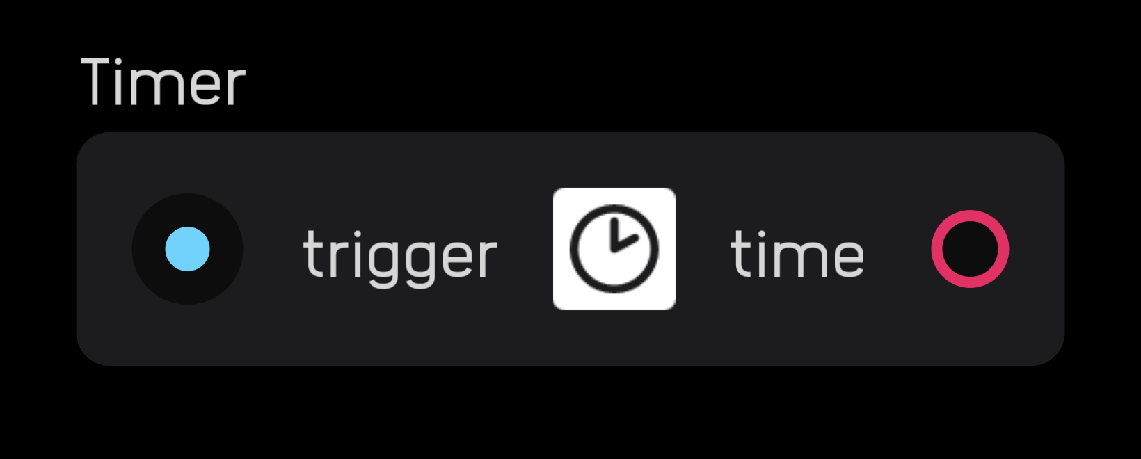
The timer node outputs elapsed time in seconds since its last reset. The node resets on the rising edge of an incoming gate signal.
The timer output increases smoothly from second to second with functional precision of 1/sampleRate seconds.
zero cross
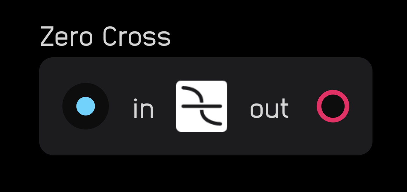
The zero cross node counts the time between two zero-crossings and outputs that value as a hz signal. To be counted as a zero-crossing, the signal must either pass through 0 or equal 0 at some point during its cycle.
Math Nodes
Math nodes are among the most powerful and versatile nodes in Audulus. They perform mathematical operations, logic, and basic programming functions.
expr
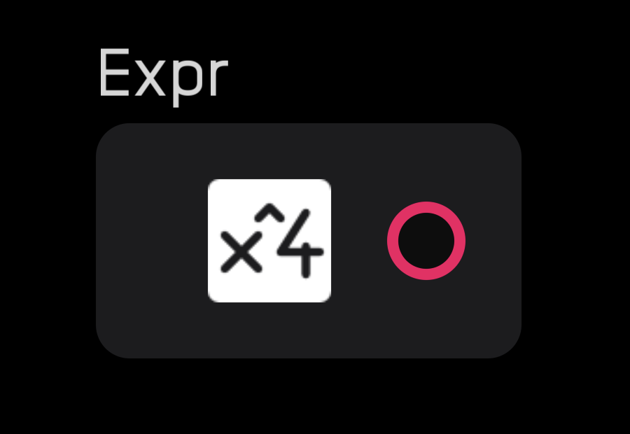
The expr node is the most versatile node, with 40 operators and functions that can be combined in many ways. It performs math and basic programming operations.
Double-clicking on any input creates an expr node.
Enter equations into the inspector panel without an = sign. You can drag and drop functions into the text field or type them directly.
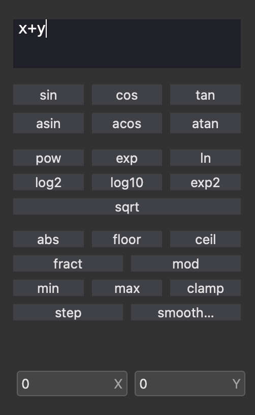
Entering letters or words creates variables as inputs. Variables are case-sensitive (x is not the same as X). Spaces and underscores are not allowed. For long variables, use camelCase (e.g., thisIsALongVariable).
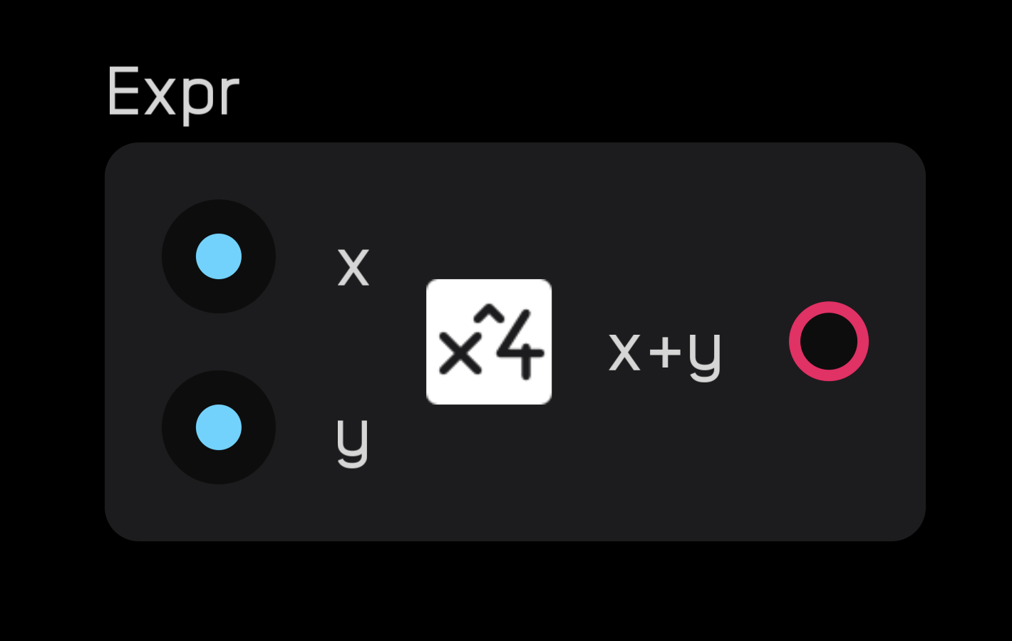
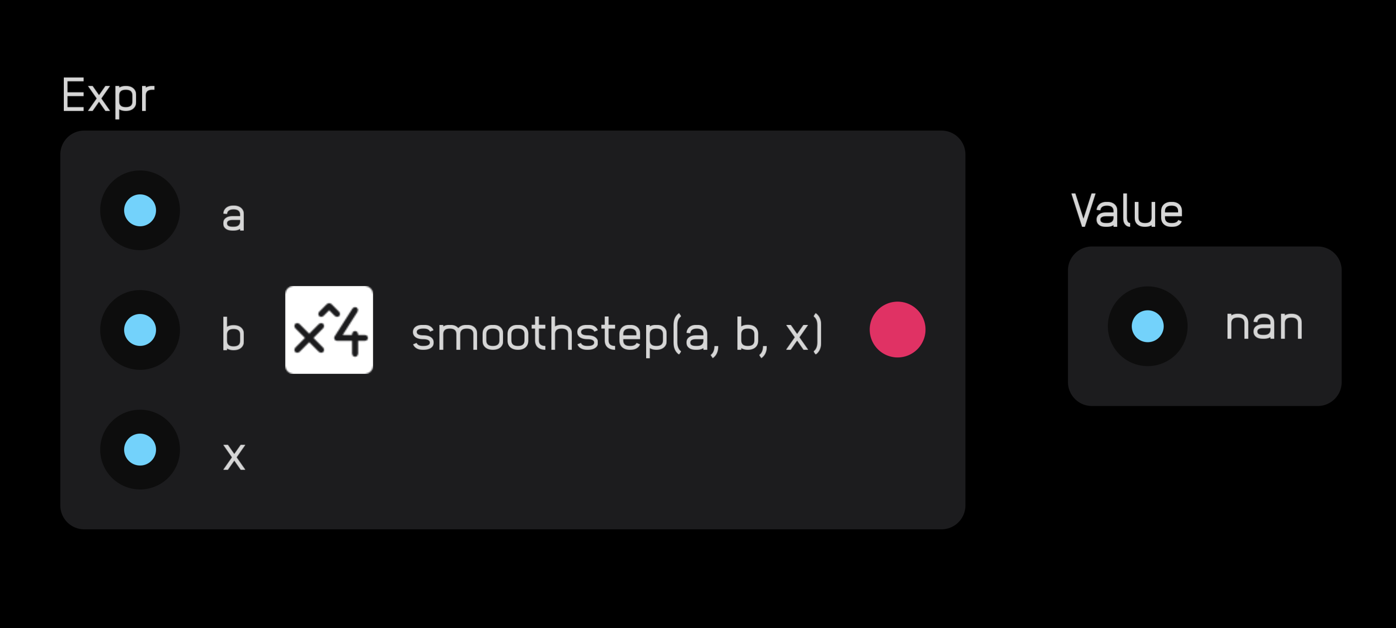
If an expression results in NaN (Not a Number), the node displays an error message.
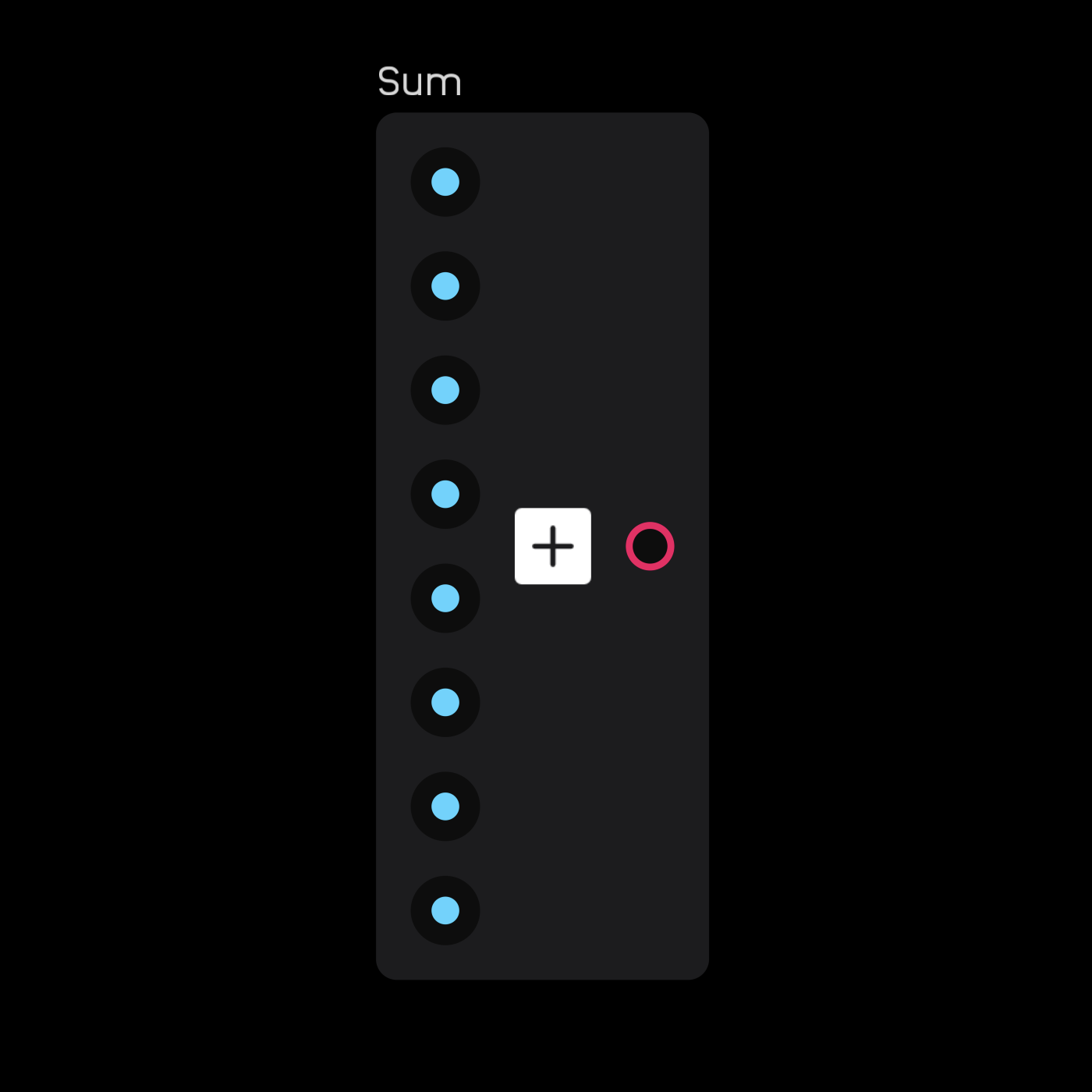
sum
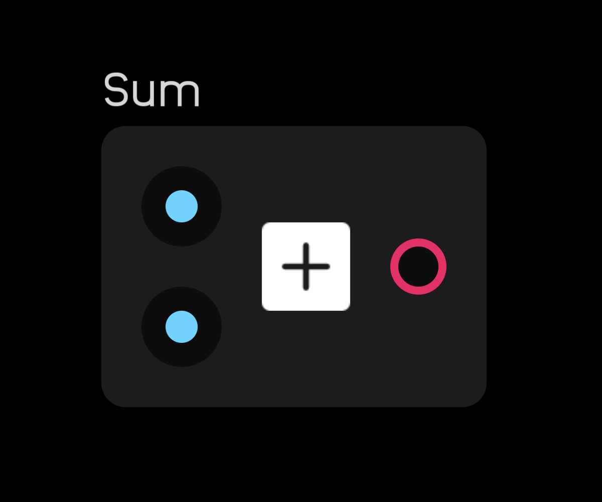
The sum node adds two or more signals together.
In the inspector panel, specify how many channels to add (maximum: 256). The sum node can be expanded to have multiple inputs.
product
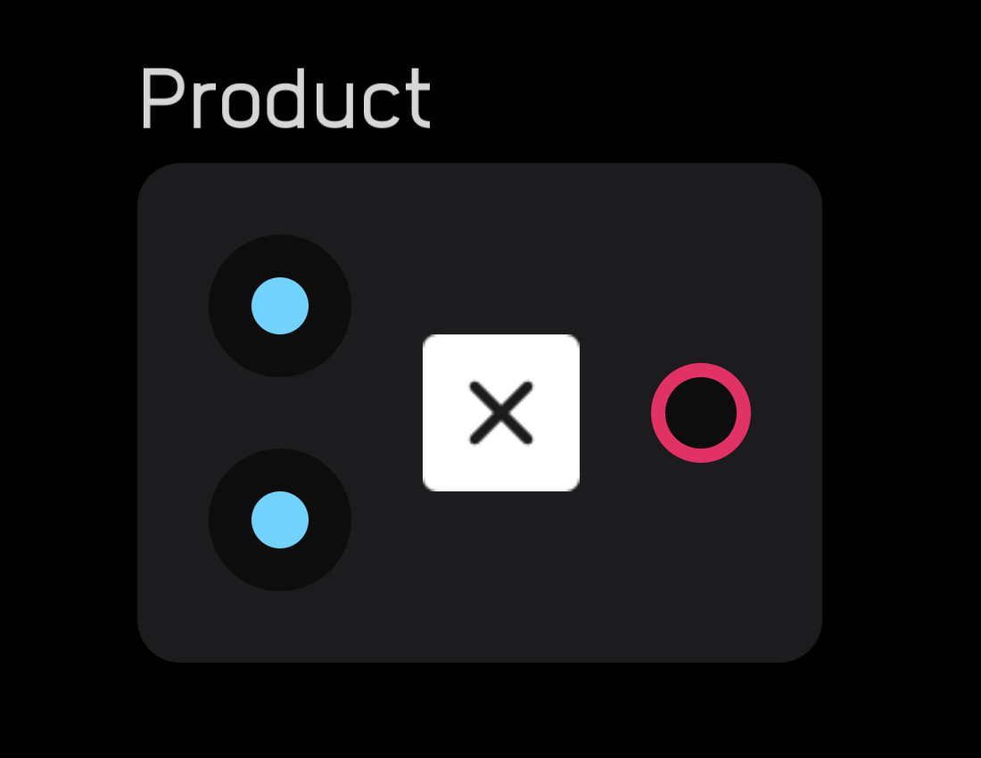
The product node multiplies two or more signals together.
In the inspector panel, specify how many channels to multiply (maximum: 256). The product node can be expanded to have multiple inputs.
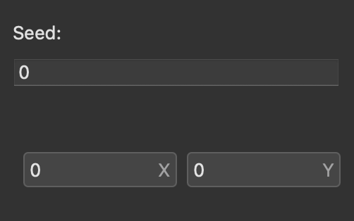
random
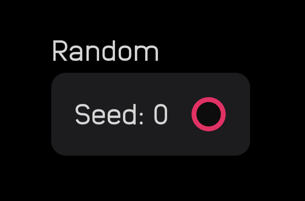
The random node outputs a new random number between 0 and 1 for every sample, producing white noise.
The seed value can be changed in the inspector panel. Changing the seed is necessary when you have two or more random nodes in a patch and want them to produce different random number sequences.
Meter Nodes
Meter nodes display information about signals, providing visual feedback and debugging capabilities.
meter
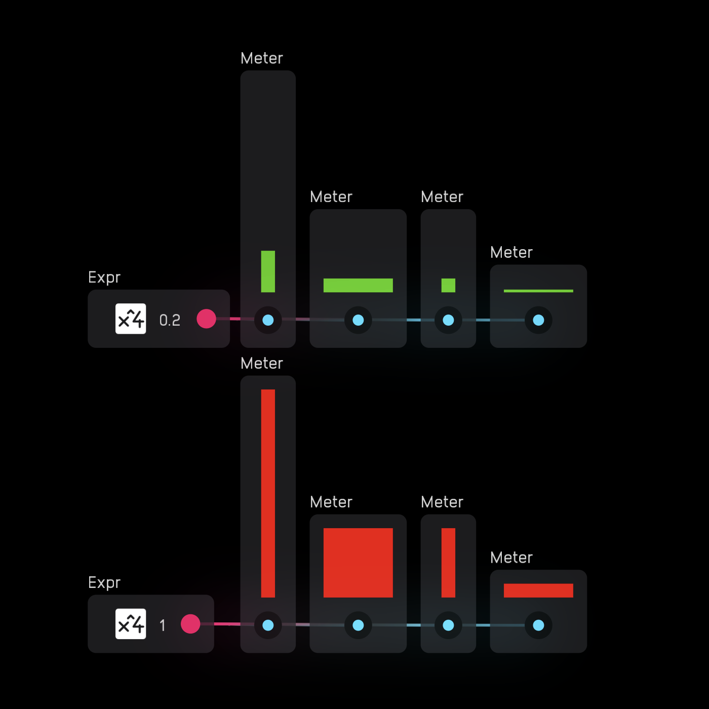
The meter node displays signal amplitude. The input works in a range of -1 to 1, though 0 to 1 displays the same as 0 to -1.
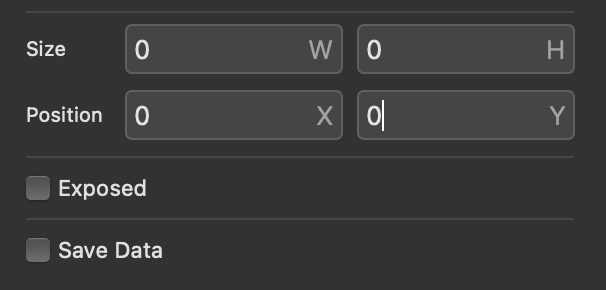
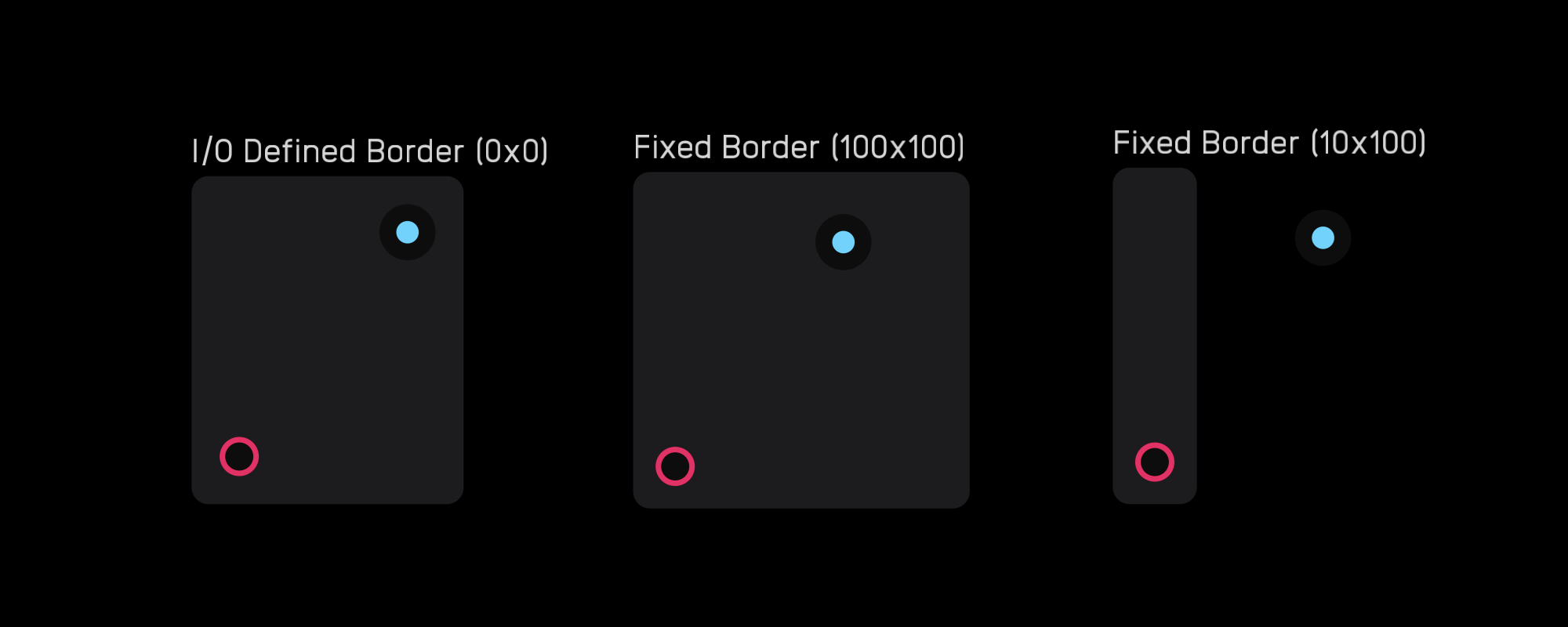
In the inspector panel, resize the meter by altering the height and width parameters. It can also be exposed.
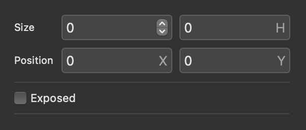
If both W and H values are 0, the node defaults to standard size. The node can be resized but not rotated.
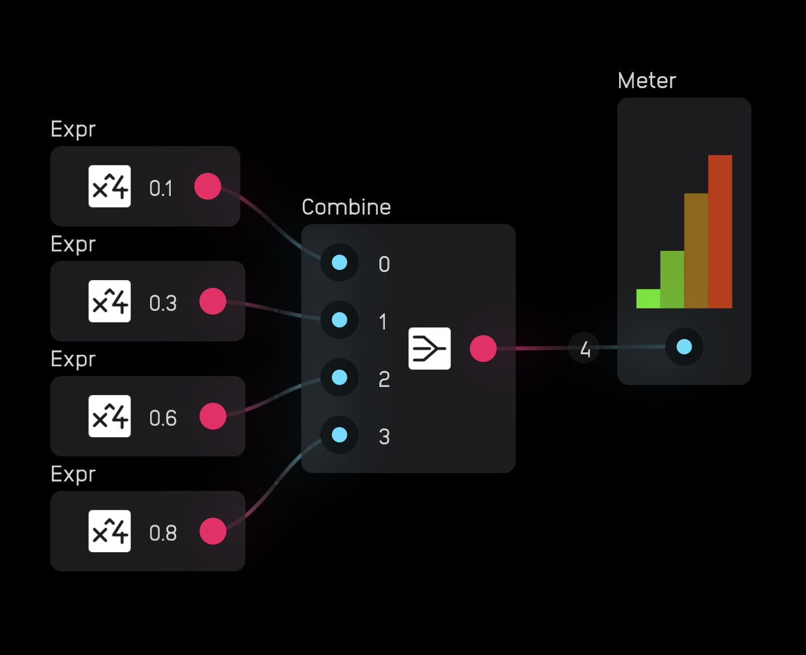
When you wire a poly signal to a meter node, it automatically creates one meter per channel.
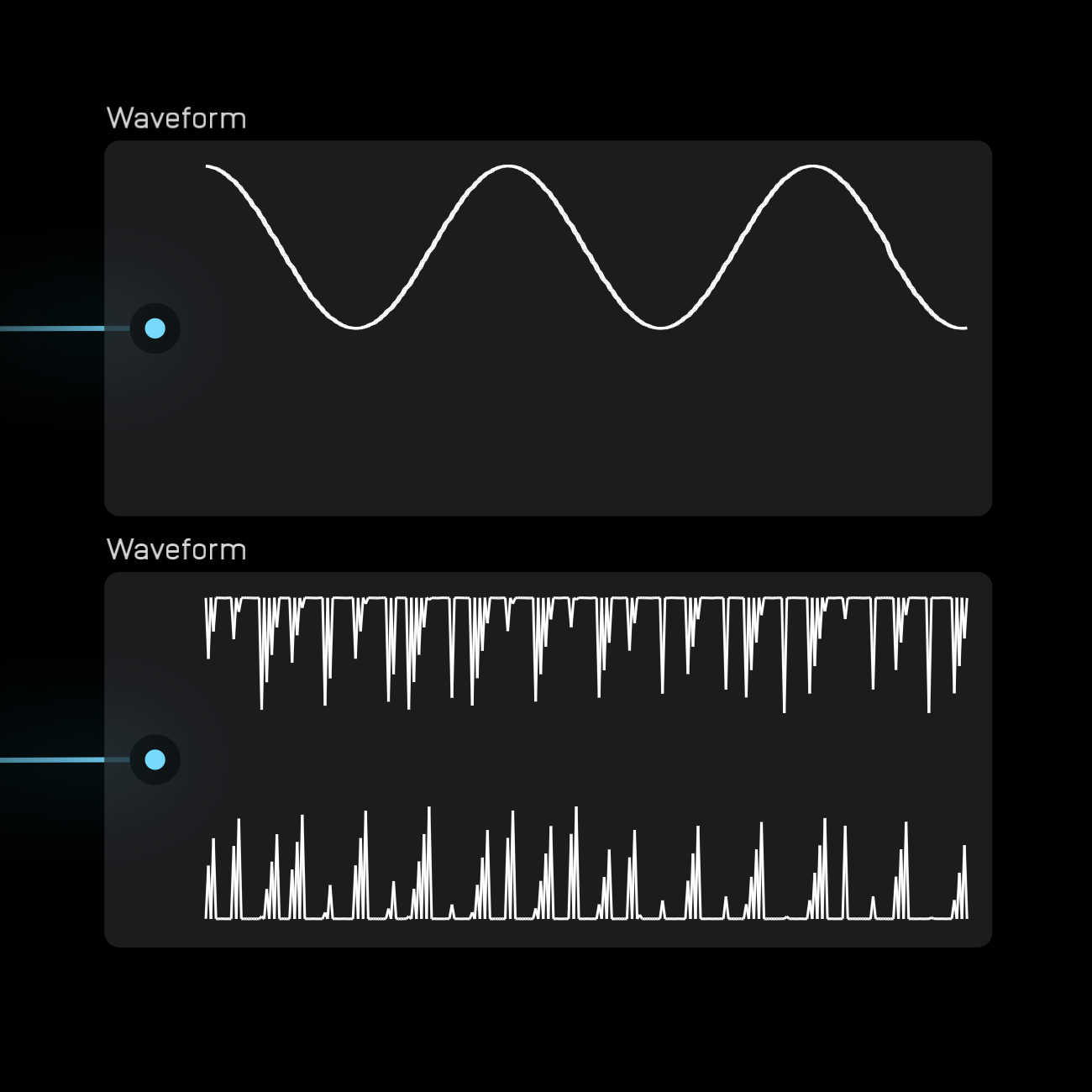
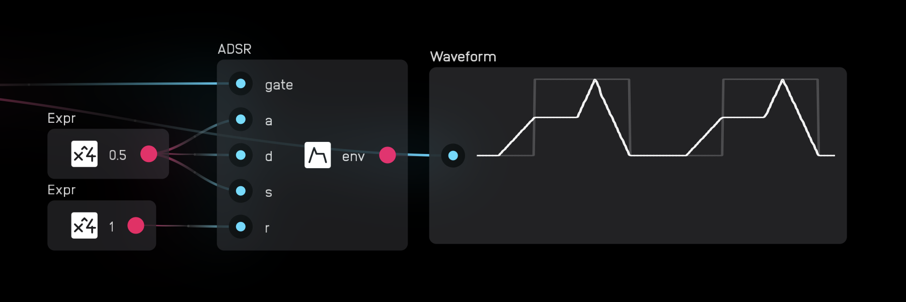
waveform
The waveform node displays signals changing over time. It has a fixed 5-second window and moves from left to right.
Since it works with the audio range, the top limit is 1, the center is 0, and the bottom is -1.
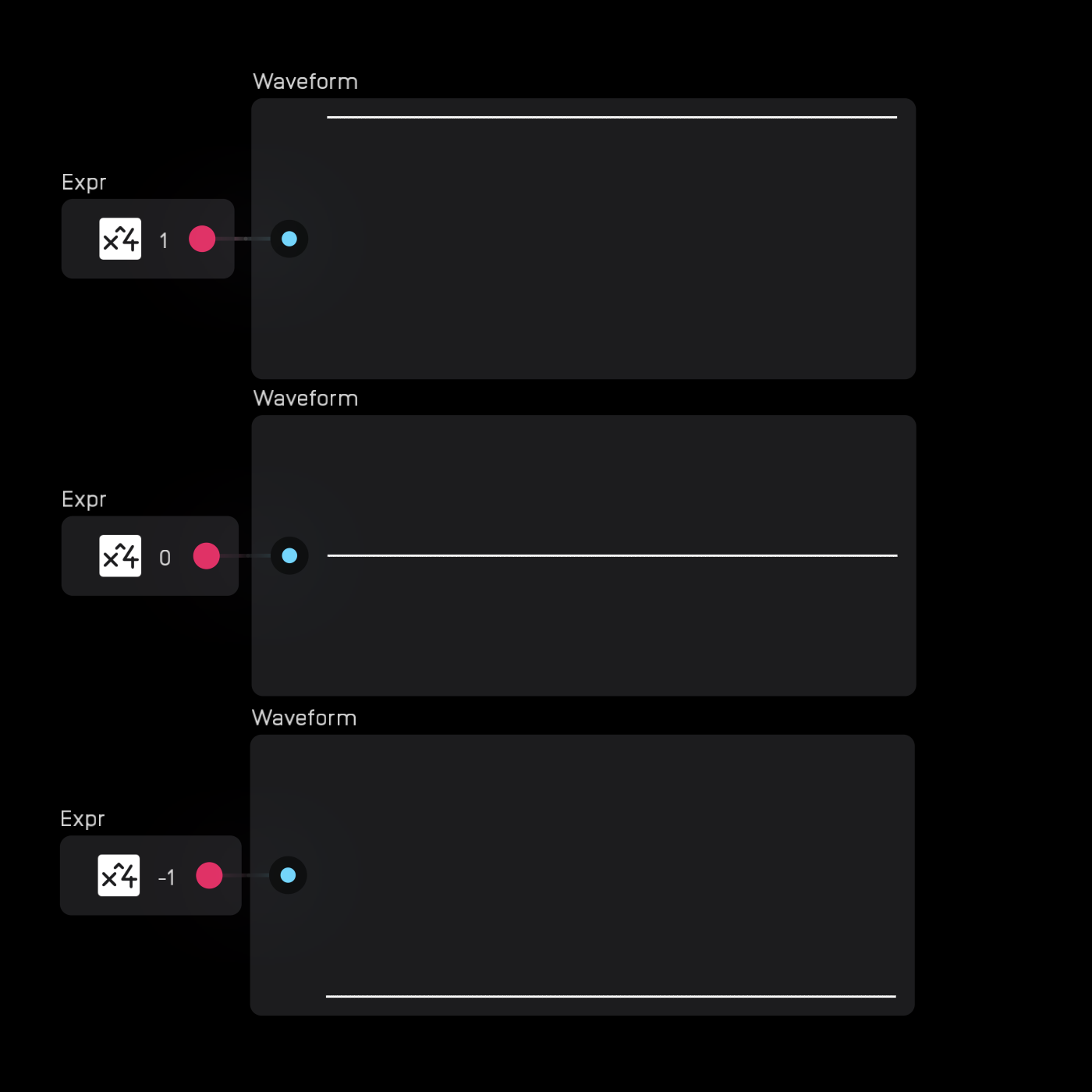
The waveform node works best with low-frequency signals. For audio-rate signals, use a scope node.
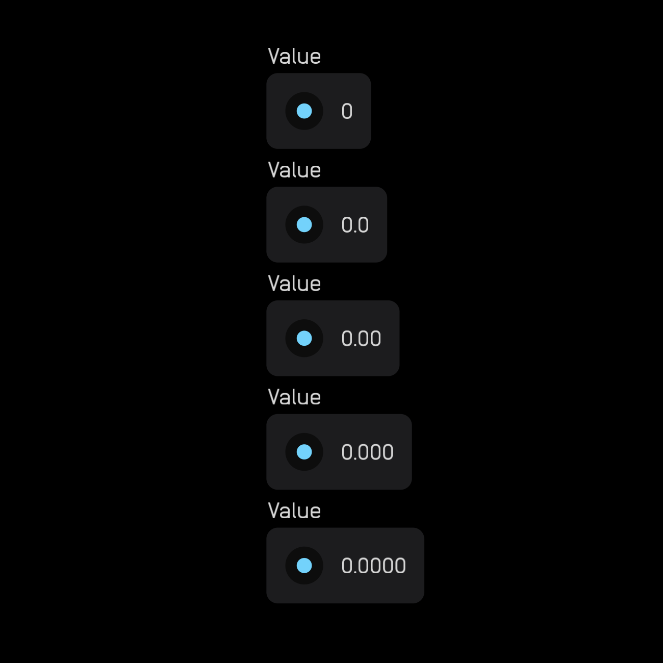
value
The value node displays the current value of any signal.
In the inspector panel, set precision from 0 to 0.0000 and choose alignment: Left, Right, or Center. The value node can also be exposed.
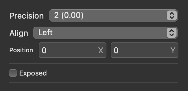
Changing precision is useful for UI displays. For example, a sequencer's current step display should be a whole number, not a decimal.
When you wire a poly signal to a value node, it automatically creates one value display per channel.
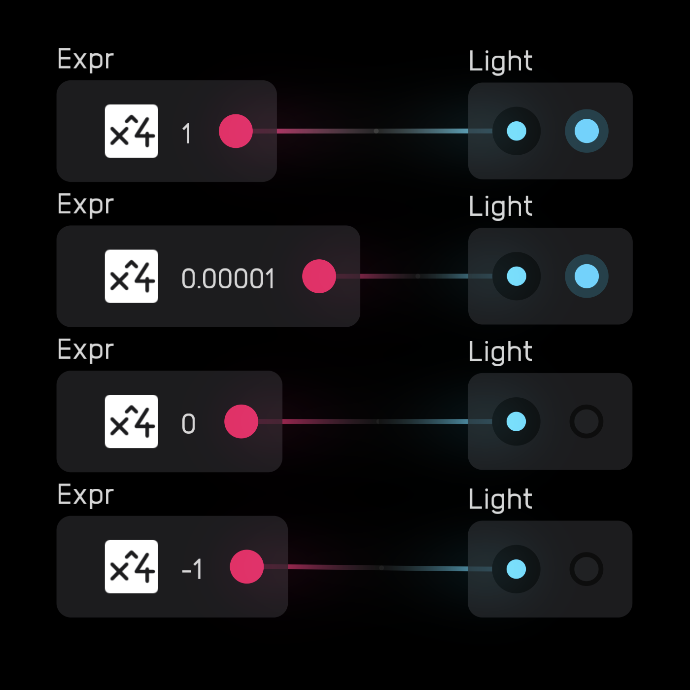
light
The light node turns on when the incoming signal is high (any non-zero positive number). Otherwise, it stays off.
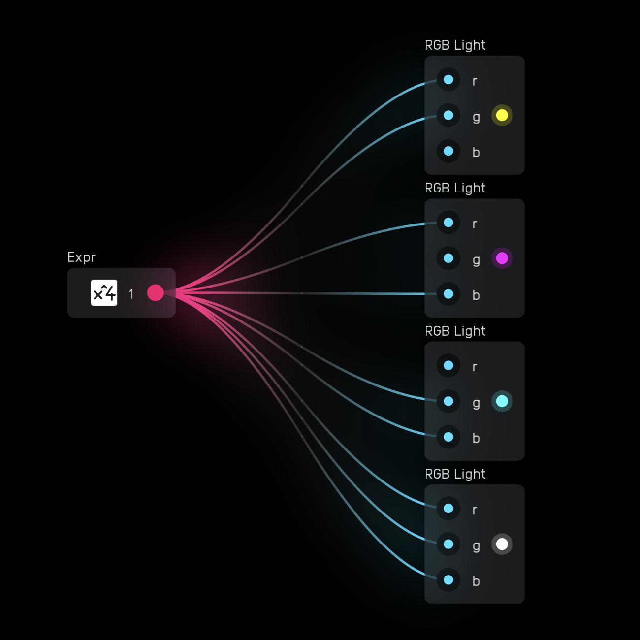
rgb light
The rgb light node has three inputs (0 to 1): red r, green g, and blue b.
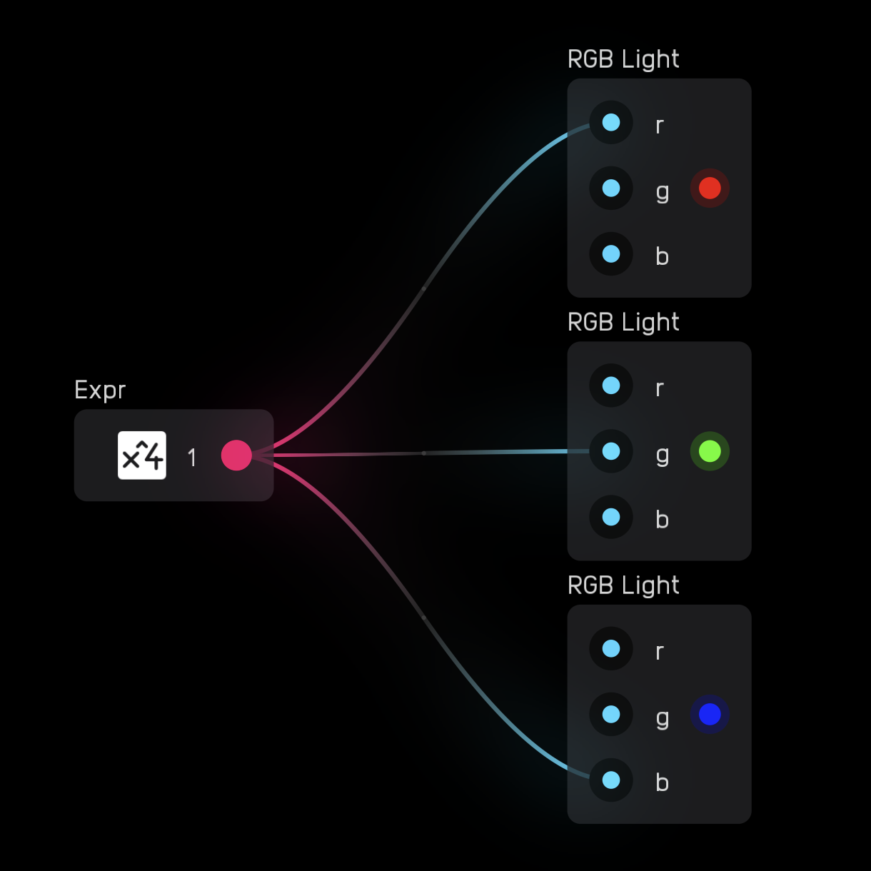
Each input uses a mod signal. When the signal is 0, the light is off. When the signal is 1, the light is fully on.
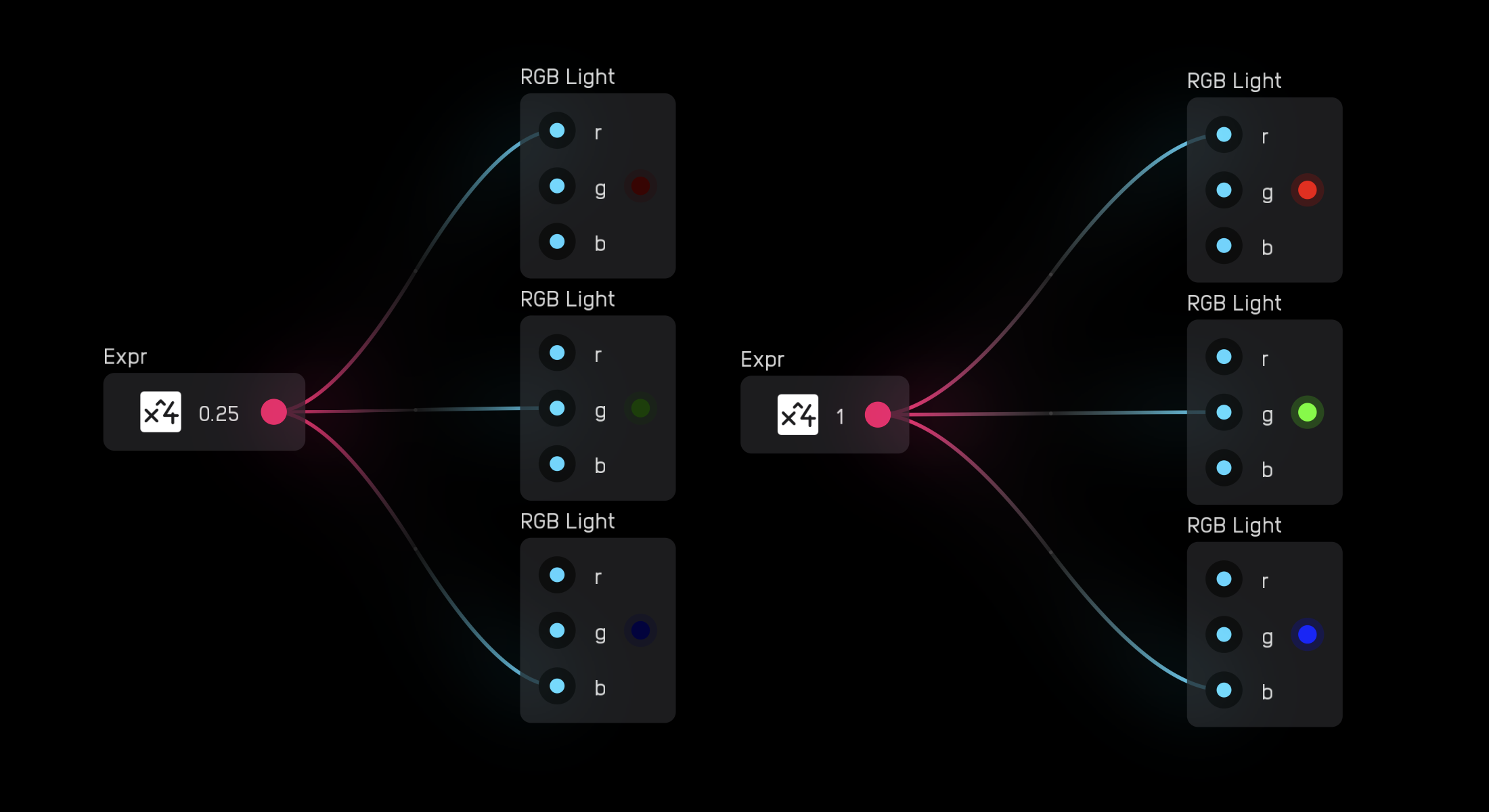
Colors can be mixed by sending different values to each input.
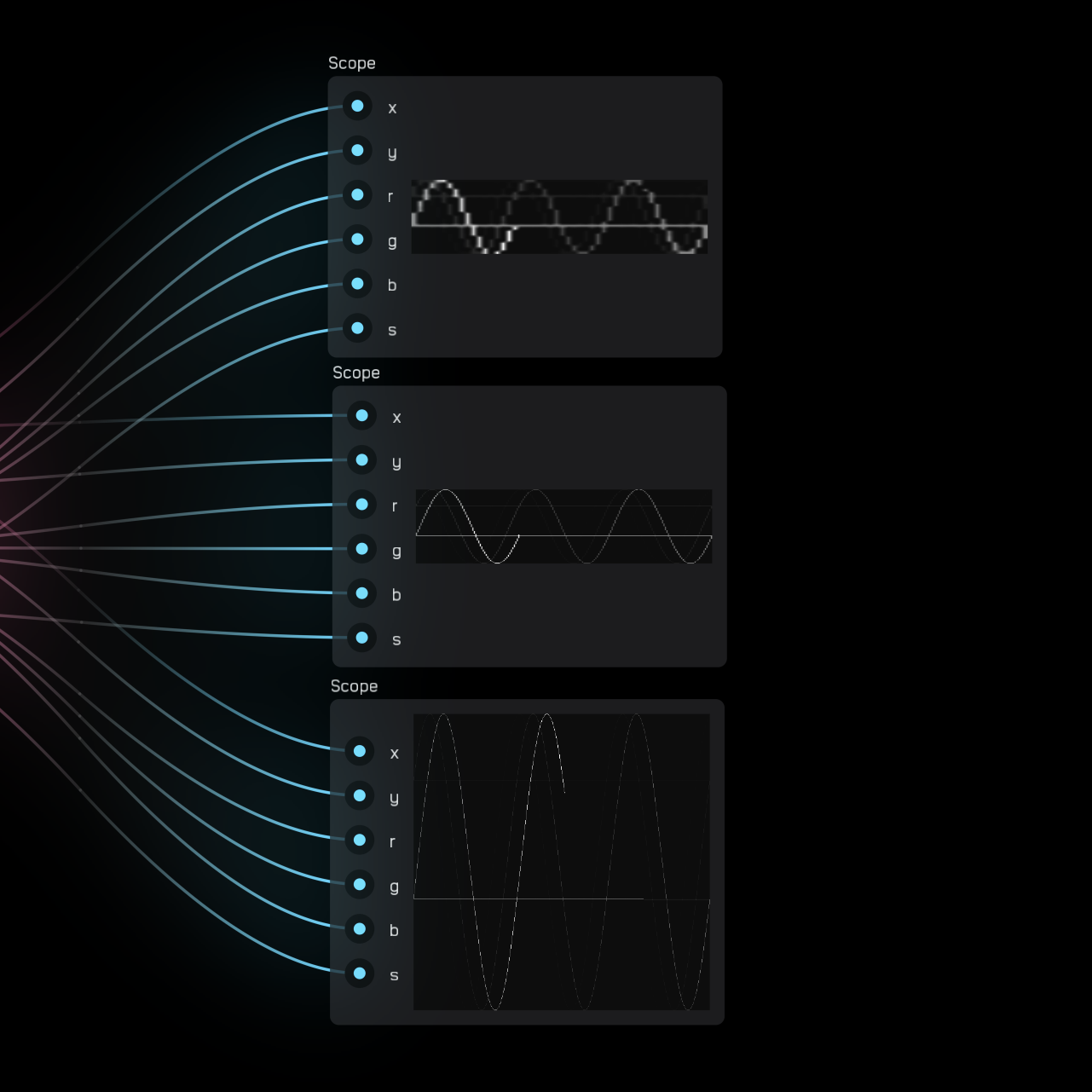
scope
The scope node visualizes high-frequency waveforms, phase relationships, and Lissajous curves that cannot be seen with the waveform node.
A cursor draws a dot with color {r, g, b} at coordinates (x, y), where both x and y range from -1 to 1. The point (0, 0) is the center of the display.
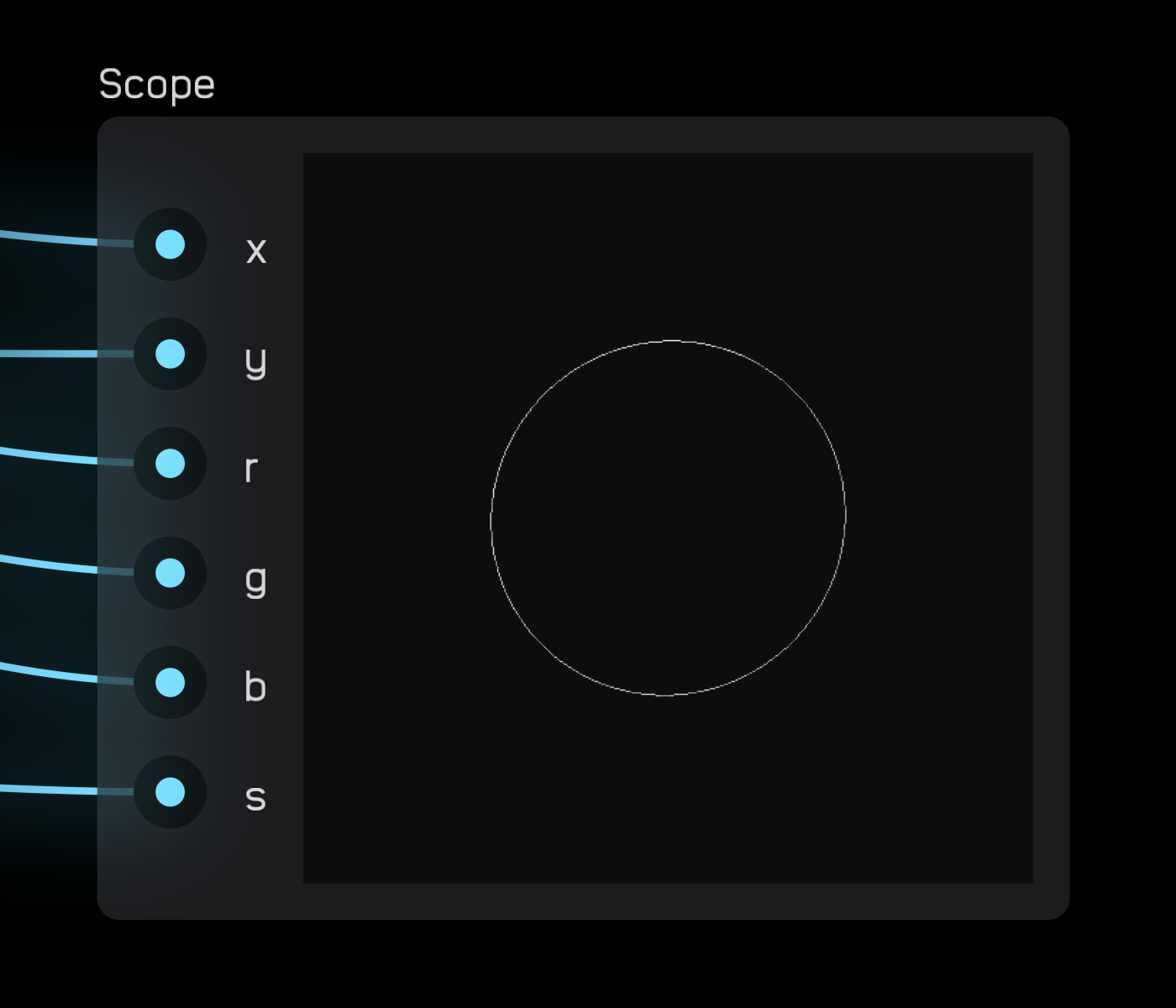
The s variable measures line persistence, where 0 shows only the current cursor position and 1 makes the line persist infinitely. Values between 0 and 1 cause the line to fade gradually.
In the scope node's inspector panel, change both the Size and resolution (Image Size).
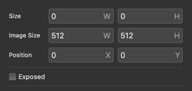
The default size is W = 200 and H = 200 with an image size of W = 512 and H = 512. For a crisp, clean line, the Image Size should be at least double the Size parameter.
canvas
The canvas node allows you to draw vector graphics using Lua scripting. Audulus has its own custom vector graphics library called VGER, which is the same library used to draw all patchbay graphics—knobs, sliders, wires, ports, modules, etc.
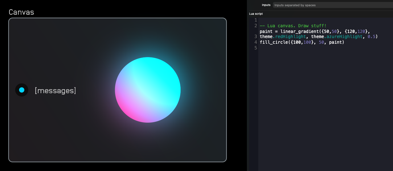
[messages] port: When you load a canvas node, you'll see a glowing gradient circle and a [messages] port. This port has a single purpose: to receive string messages from DSP nodes using the send() and receive() signal type. This is useful for drawing large chunks of data faster than would otherwise be possible, such as audio waveforms or data that would require many ports.
Create your own input ports in the inputs field at the top of the Inspector Panel. Enter each variable name separated by a space.
Code Editor: Use the code editor to write your Lua script and draw vector graphics in the canvas area.
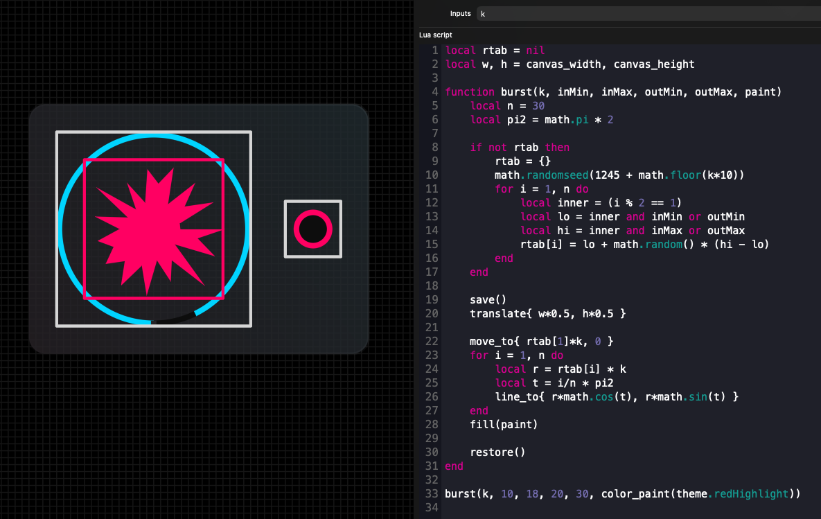
Available Functions: Below the code editor are all available custom Lua functions for canvas node. Use these as reference, or drag and drop them directly into your code from the inspector panel—you'll see code editing input fields for available parameters that you can tab through.
paint = color_paint { r, g, b, a }
paint = linear_gradient( {start_x, start_y}, {end_x, end_y}, {r, g, b, a}, {r, g, b, a}, glow)
paint = radial_gradient( {center_x, center_y}, inner_radius, outer_radius, {r, g, b, a}, {r, g, b, a}, glow)
fill_circle( {x, y}, radius, paint)
stroke_circle( {x, y}, radius, width, paint)
stroke_arc( {x, y}, radius, width, rotation, aperture, paint)
stroke_segment( {ax, ay}, {bx, by}, width, paint)
fill_rect( {min_x, min_y}, {max_x, max_y}, corner_radius, paint)
stroke_rect( {min_x, min_y}, {max_x, max_y}, corner_radius, width, paint)
stroke_bezier( {ax, ay}, {bx, by}, {cx, cy}, width, paint)  -- stroke a quadratic bezier
text("hello world!", {r,g,b,a})
min, max = text_bounds("hello world!")
text_box("lorem ipsum...", break_row_width, {r,g,b,a})
min, max = text_box_bounds("lorem ipsum...", break_row_width)
move_to {x, y}  -- moves the pen for path fills
line_to {x, y}  -- adds a line to the path
quad_to({bx, by}, {cx, cy})  -- adds a quadratic bezier segment to the path
fill(paint)  -- fills the current path
translate {tx, ty}  -- translates coordinate system
scale {sx, sy}  -- scales coordinate system
rotate(theta)  -- rotates coordinate system
save()  -- saves transform state
restore()  -- restores transform state
canvas_width  -- width of drawing area
canvas_height  -- height of drawing area
theme.text  -- text color
theme.grooves  -- black background color
theme.azureHighlight  -- azure highlight color
theme.azureHighlightDark  -- dark azure highlight color
theme.azureHighlightBackground  -- azure background color
theme.greenHighlight  -- green highlight color
theme.greenHighlightDark  -- dark green highlight color
theme.greenHighlightBackground  -- green background color
theme.redHighlight  -- red highlight color
theme.redHighlightDark  -- dark red highlight color
theme.redHighlightBackground  -- red background color
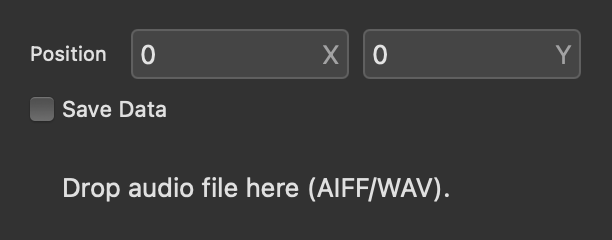
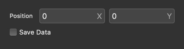
Options: Below the functions are options to change the canvas node Size and enable Save Data to save globals across patch loads.
MIDI Nodes
MIDI nodes send and receive MIDI signals in and out of Audulus, connecting to external controllers, hardware, and DAWs.
keyboard
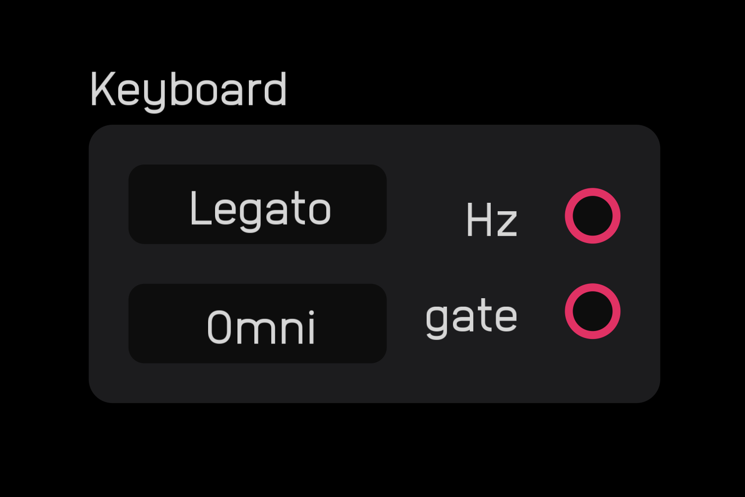
The keyboard node receives input from MIDI keyboards, DAWs, and other MIDI input devices.
It outputs a Hz value for the note and a gate signal for note on/off. The gate height represents velocity.
note send
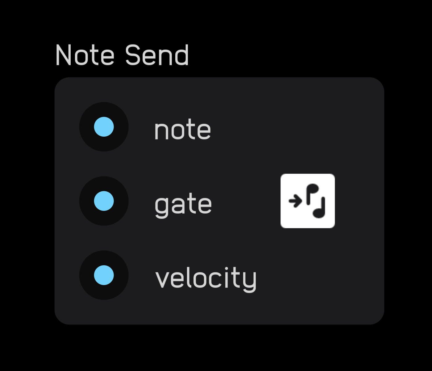
The note send node sends MIDI note, gate, and velocity data from Audulus to external instruments.
cc send
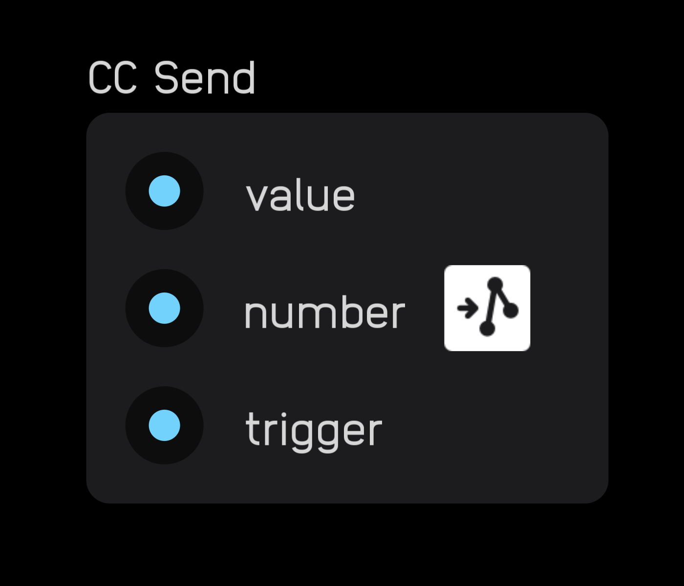
The cc send node sends MIDI CC values from Audulus to external instruments.
When the trigger input goes high, the signal at the value input is sent to the specified CC number.
trigger
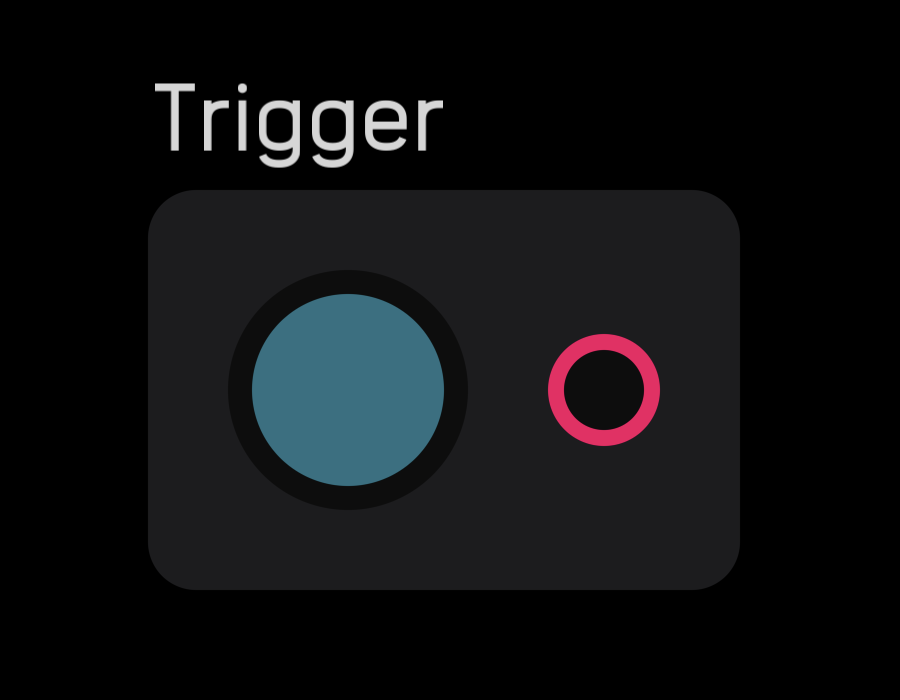
The trigger node outputs a gate when its button is pressed. The button can be clicked, tapped, or assigned to an external hardware MIDI signal in MIDI mapping mode.
Mod Nodes
Mod nodes manipulate signal levels, create custom response curves, and extract amplitude envelopes.
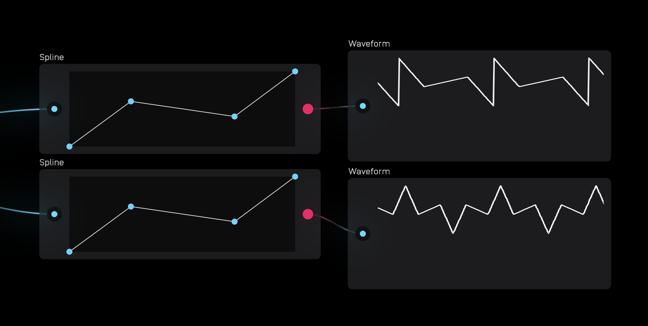
spline
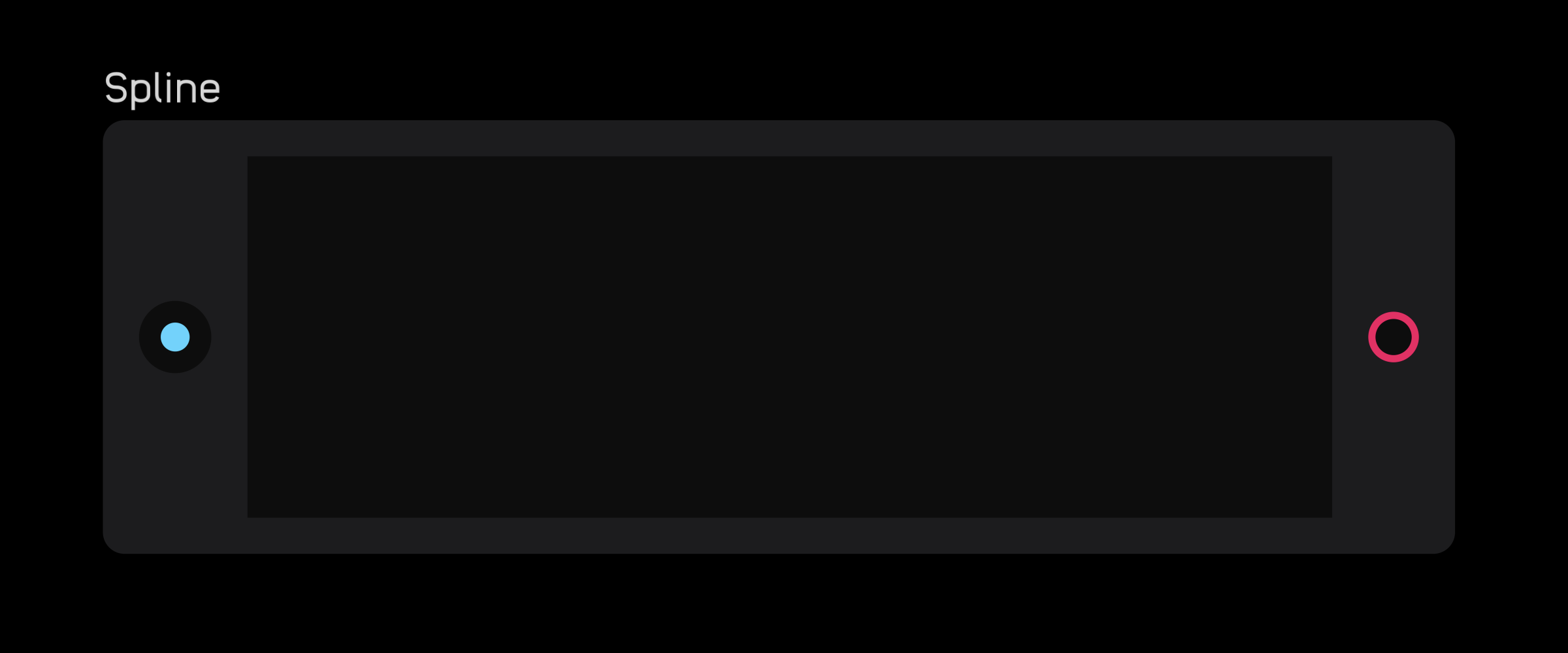
The spline node allows you to draw a line using two or more breakpoints. xand y ranges in the graph are 0 to 1. For example, if you connect a knob (also 0 to 1) to the spline input port, turning the knob will advance through the spline graph and output the current y value.
Add breakpoints by double-clicking or tapping on the blank field inside the node. Once created, they can be dragged anywhere within the field.
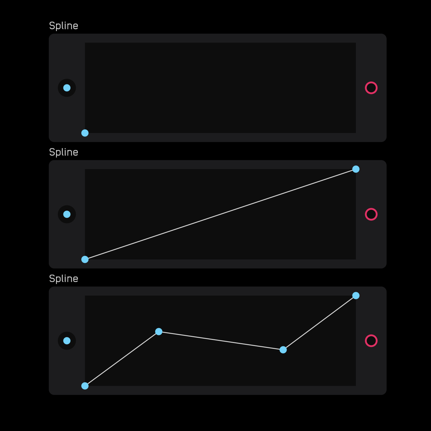
The spline node is great for creating custom LFOs.
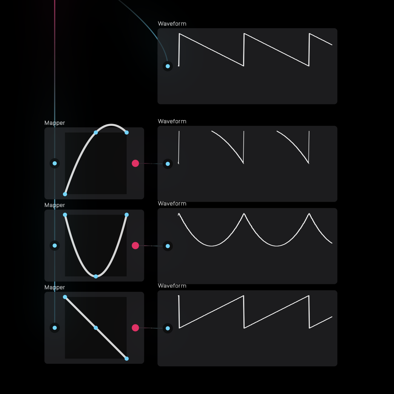
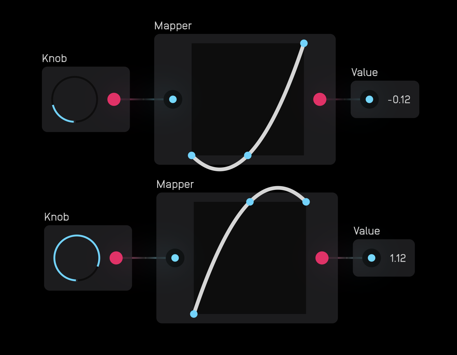
mapper
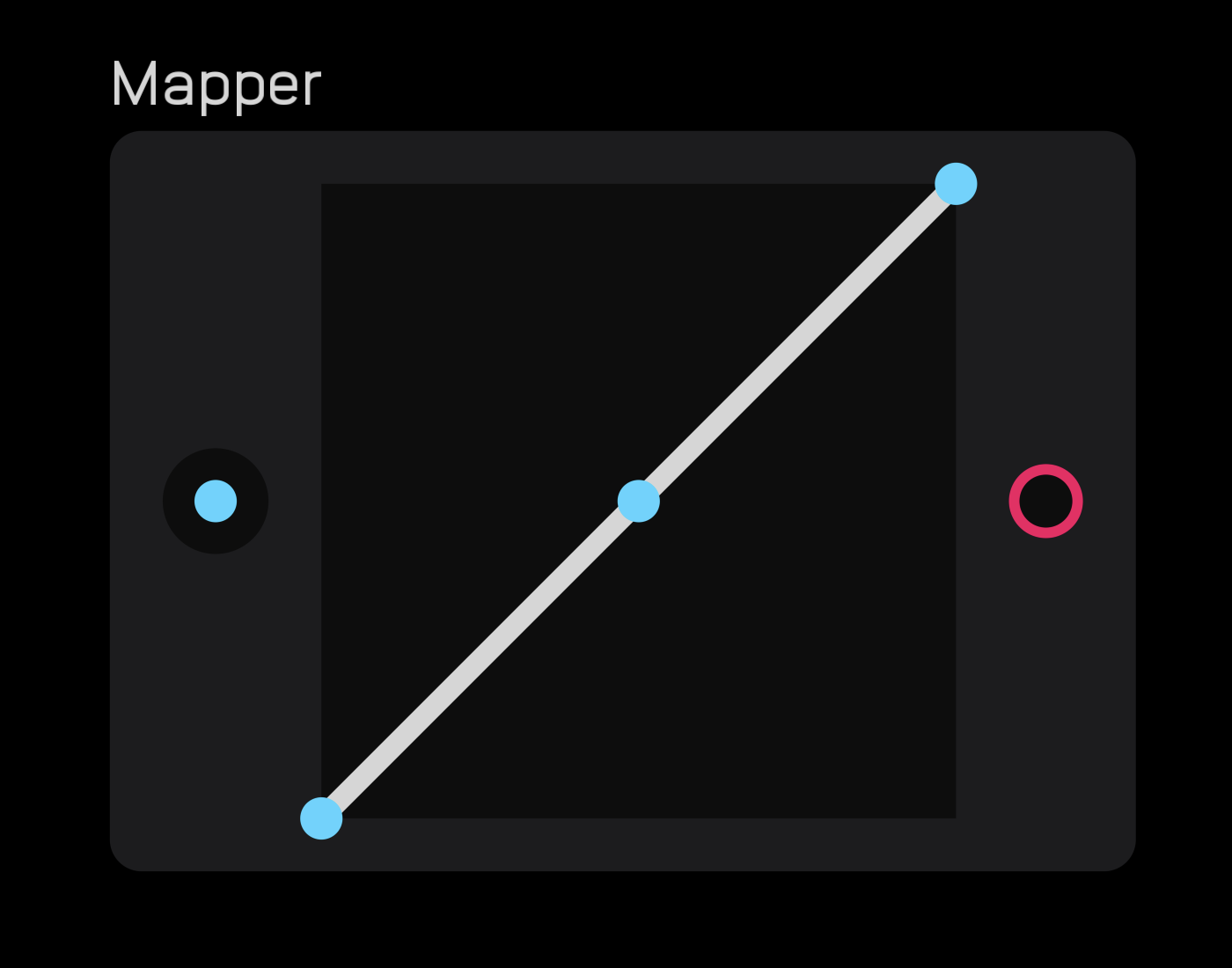
The mapper node changes the response of an incoming modulation signal based on the curve drawn in the node's field.
The coordinate system determining the output is (in, line). The bottom left of the field is (0, 0) and the top right is (1, 1). The output of the node is the y value of the line given an x input.
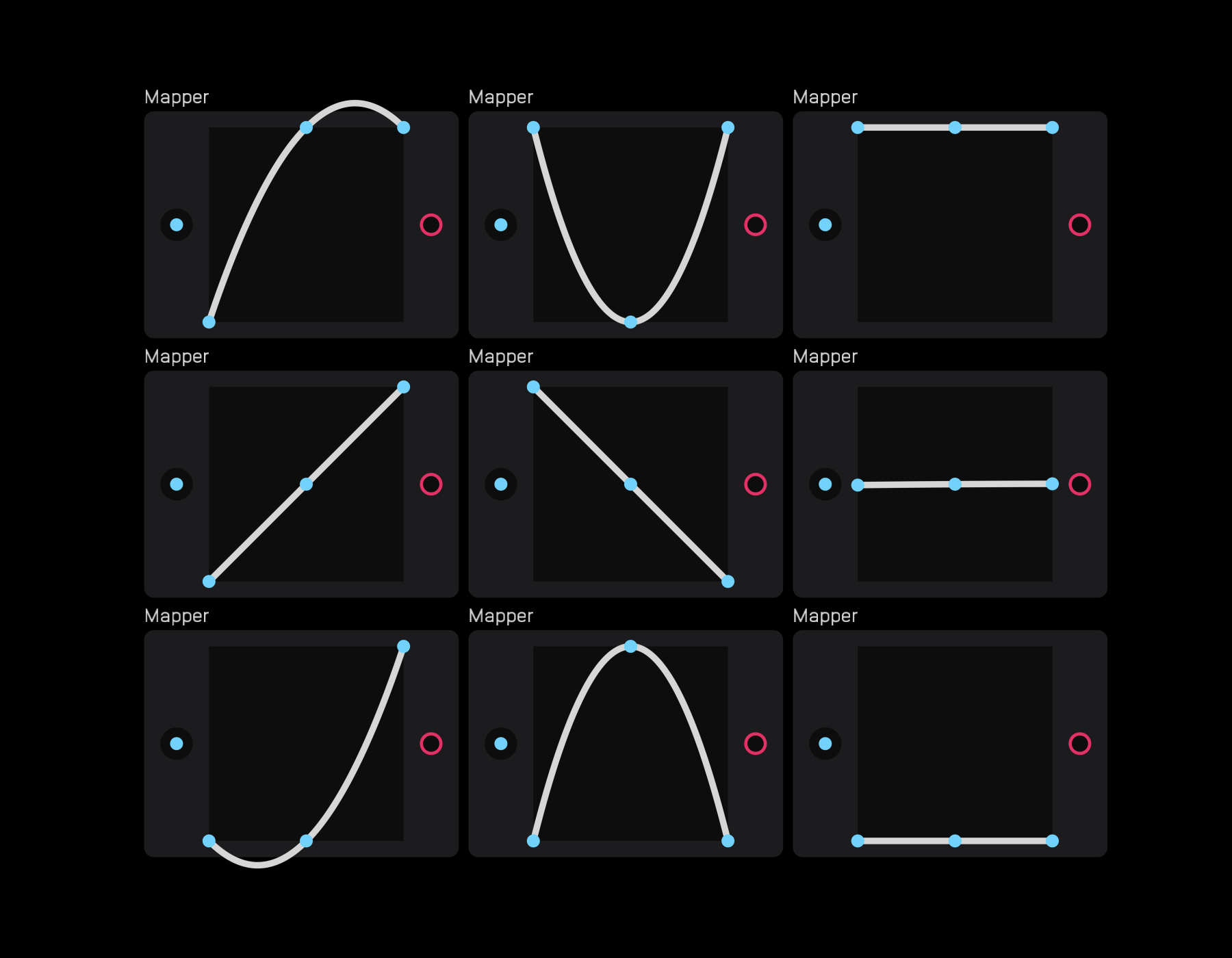
The mapper node is excellent for creating custom LFOs and overshoot effects.
env follow
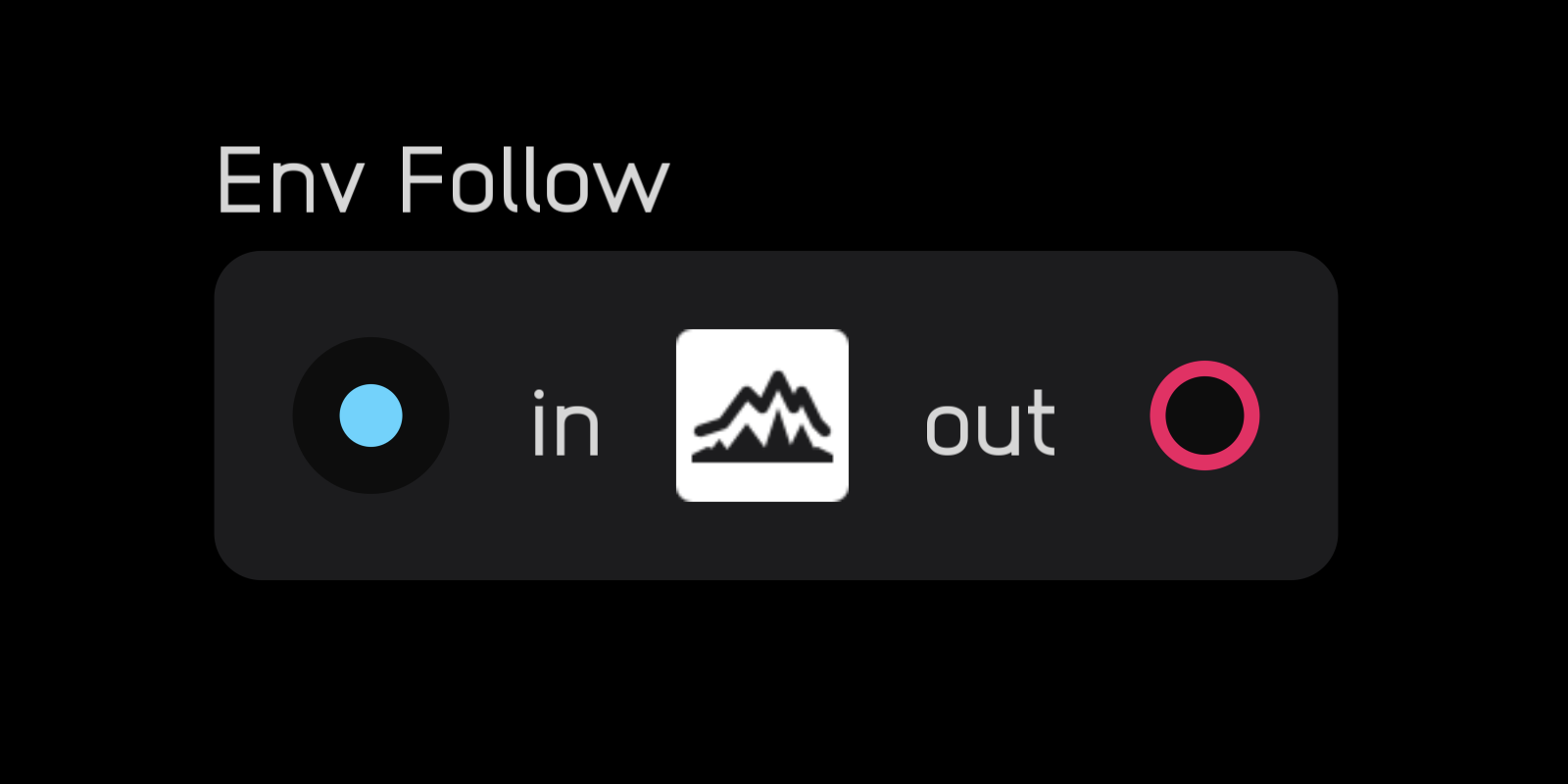
The env follow node extracts an envelope from an incoming audio signal and transforms it into a modulation signal. It does this by taking the absolute value of the incoming signal and applying a small amount of filtering to smooth transitions between samples.
adsr
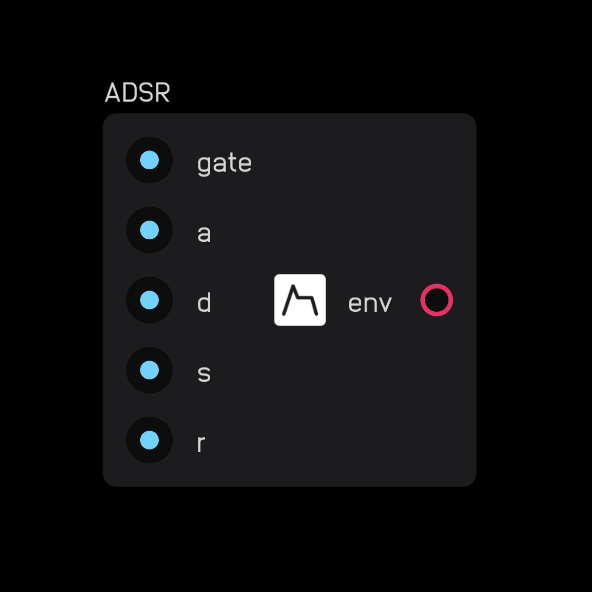
The adsr node outputs an envelope when the gate input is held high.
Inputs:
a: Attack timed: Decay times: Sustain levelr: Release time
As long as the gate input is high, the envelope output increases from 0 to gate height over a seconds, decreases to the s level over d seconds, then once the gate goes low, decreases from the s level back to 0 over r seconds.
DSP Nodes
DSP (Digital Signal Processing) nodes are essential for creating filters and manipulating signals at a low conceptual level.
unit delay
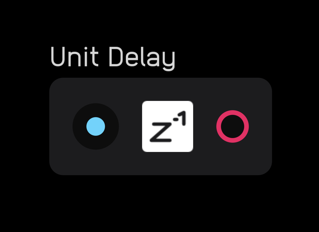
The unit delay node delays an incoming signal by one sample. It also explicitly marks where a feedback delay occurs within a feedback loop.
If a unit delay is not inserted within a feedback loop, Audulus will guess where to place it. This is usually acceptable, but in some cases like analog-modeling filters, you need to be explicit about feedback delay placement.
biquad
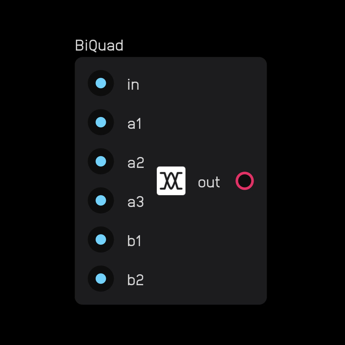
The biquad node allows you to create all types of biquadratic filters.
Calculate the coefficient inputs separately from the node using expr nodes.
low-pass
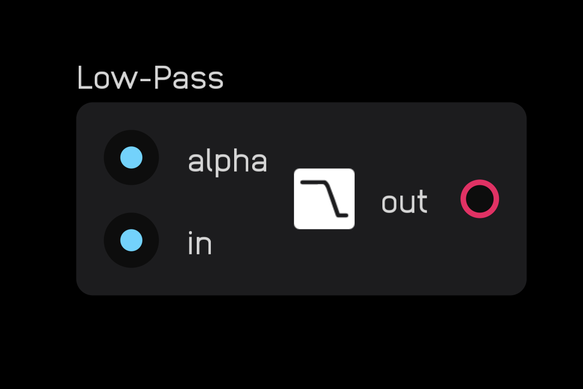
The low pass node is a simple non-resonant 6dB/oct low-pass filter. The alpha input is the smoothing factor, where 1 = no filtering and 0 = maximum filtering.
high-pass
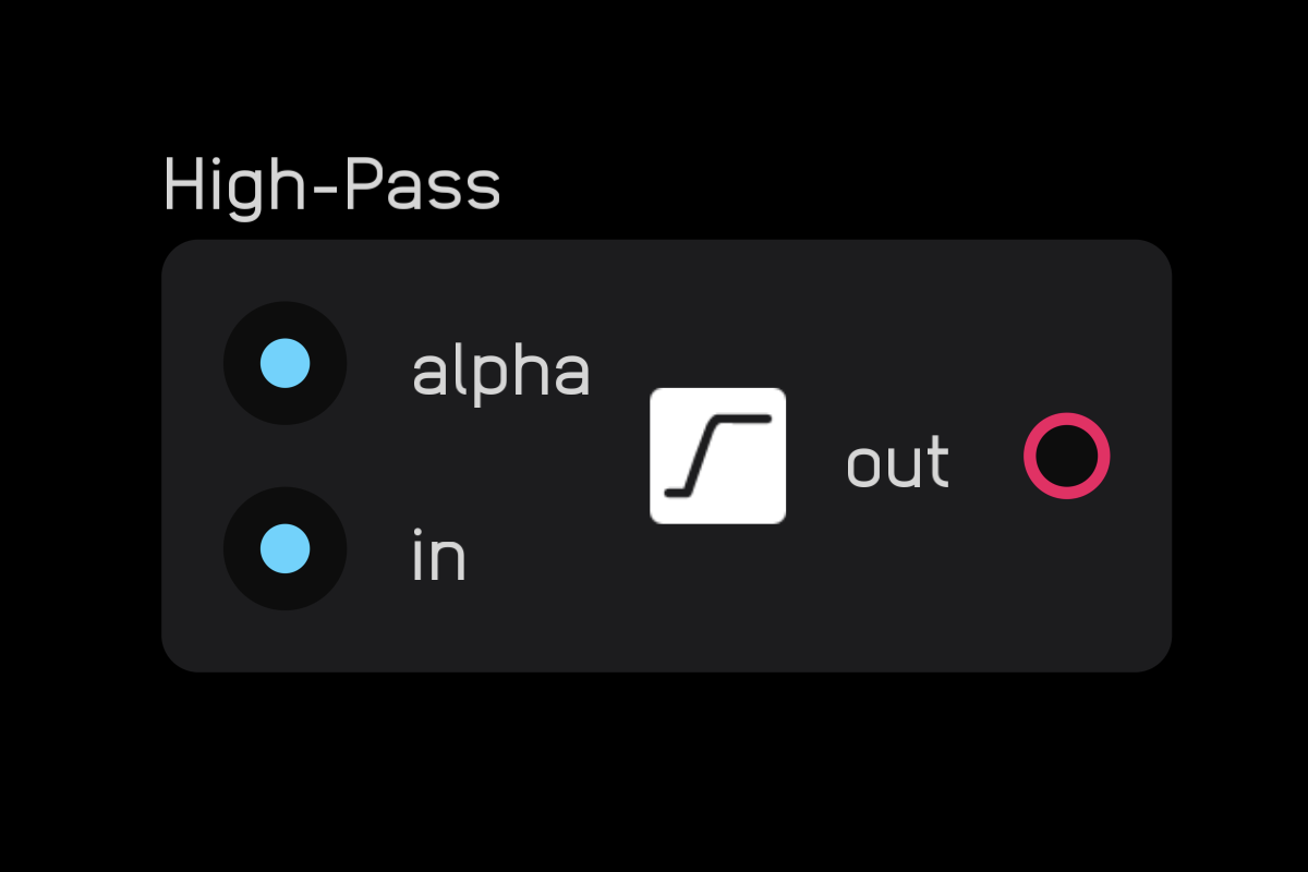
The high pass node is a simple non-resonant 6dB/oct high-pass filter. The alpha input is the smoothing factor, where 1 = maximum filtering and 0 = no filtering.
delay line
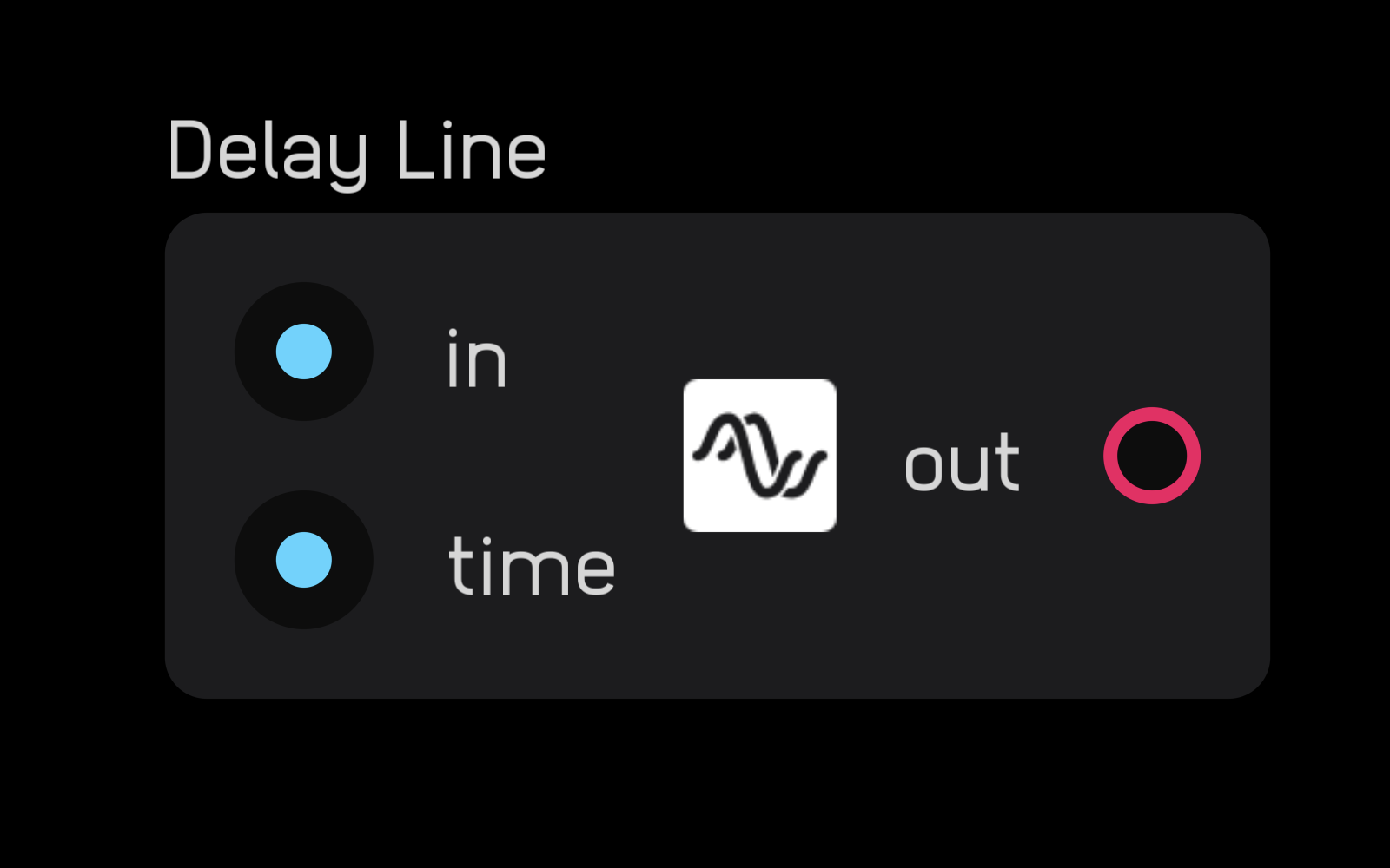
The delay line node delays an incoming signal by a set number of seconds, determined by the value at the time input.
dc blocker
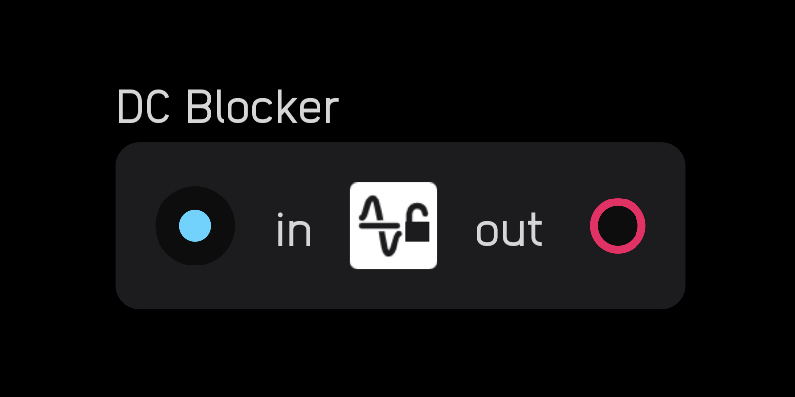
The dc blocker node removes any DC offset from an audio signal.
sample rate
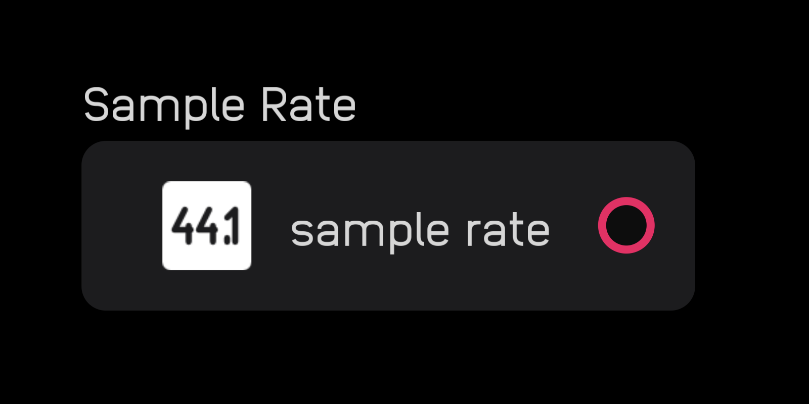
The sample rate node outputs the current sample rate in Hz.
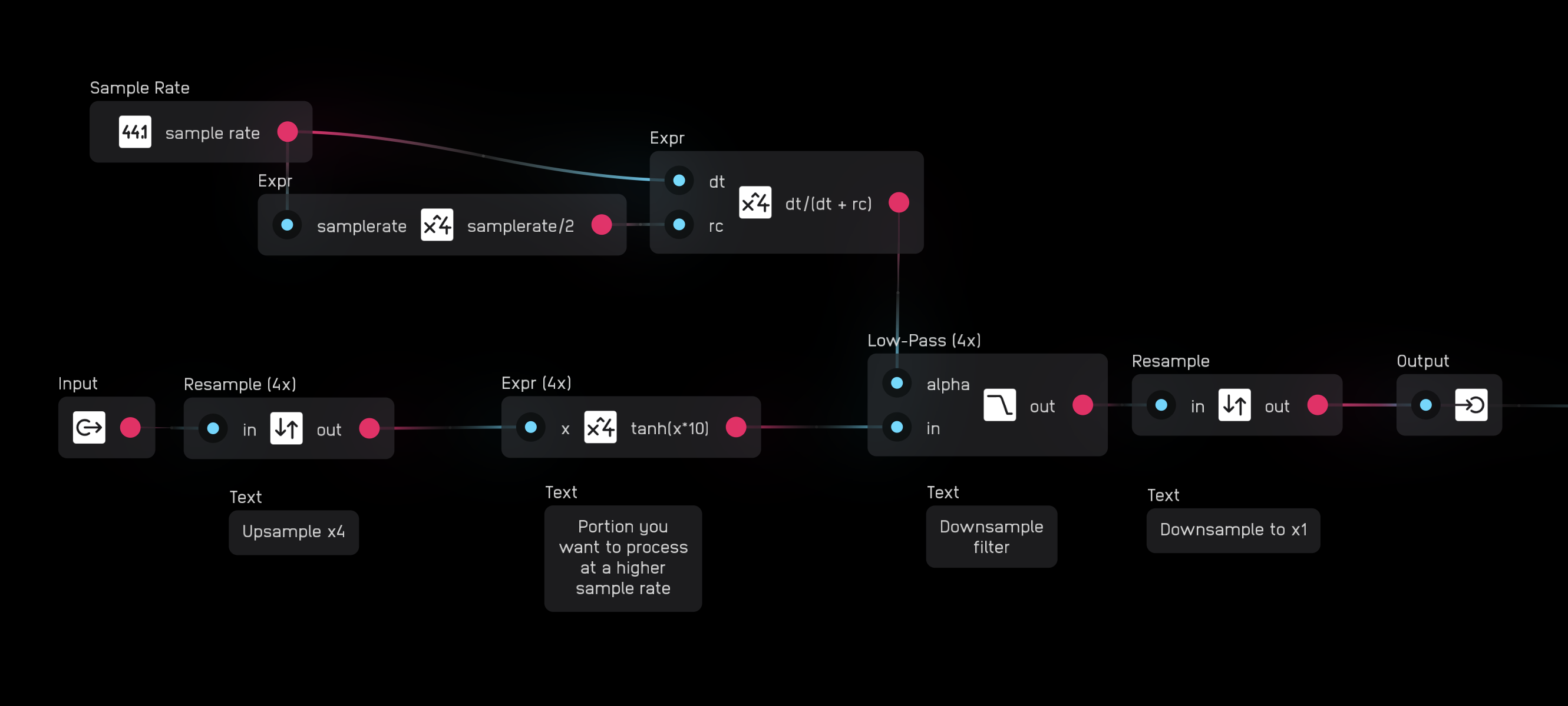
resample
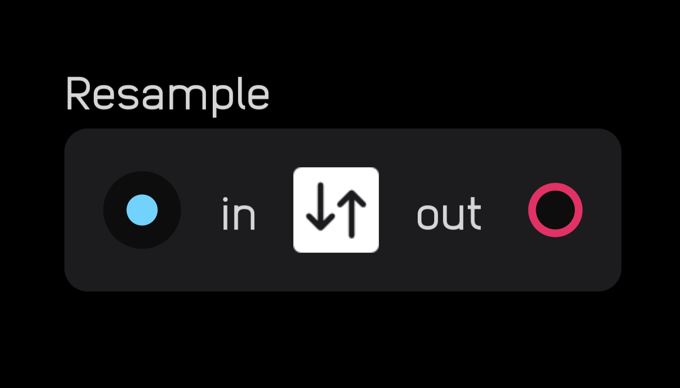
The resample node lets you run a portion of a patch at a higher sample rate (supersampling).
In the inspector panel, choose from different multiples of the base sample rate from 1× to 16×. Higher sample rates use more CPU time.
Note: the resample node should always be accompanied by a 'closing' resample node to convert back to 1x sample rate at the end of the section you wish to resample.
memory
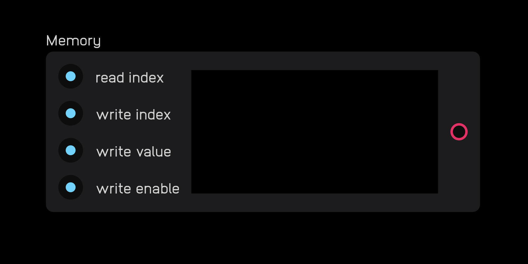
The memory node can read, write, and store audio and control signals. Information is stored as a series of samples.
DSP
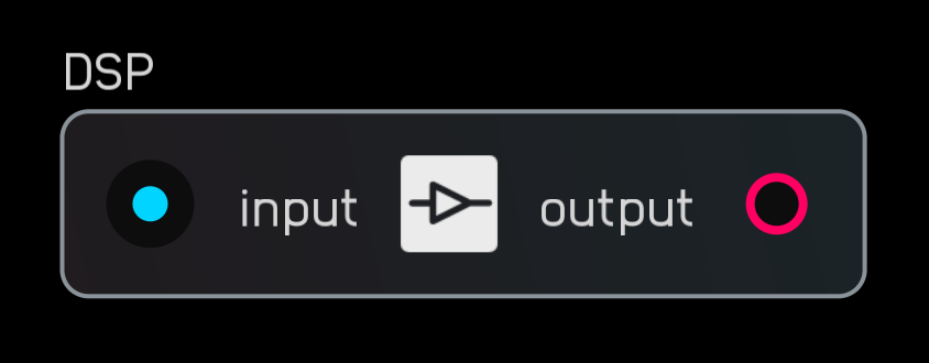
The DSP node runs Lua scripts to process audio. It can handle a wide range of tasks—oscillators, filters, dynamics, sequencers, utilities, and custom logic.
The default code block for the DSP node:
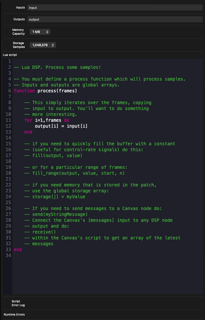
The node supports three processing modes:
Per-sample (audio rate).
Use a loop such as for i = 1, frames do output[i] = input[i] end. This is the standard method for high-quality, sample-accurate DSP.
Per-block (control rate).
Use fill(output, value) to write one value for the entire block. This is ideal for sequencers, logic, state machines, and other low-frequency operations that don't require audio-rate computation.
Data streaming to Canvas.
Use send() to emit CSV-style string data for high-throughput communication to a Canvas node. The Canvas node reads this data with receive(). This stream runs at roughly ten times the graphics frame rate, enabling responsive waveform drawing, efficient bulk data transfer, and sending text or structured data without multiple ports.
Synth Nodes
Synth nodes are low-level building blocks specific to audio synthesis.
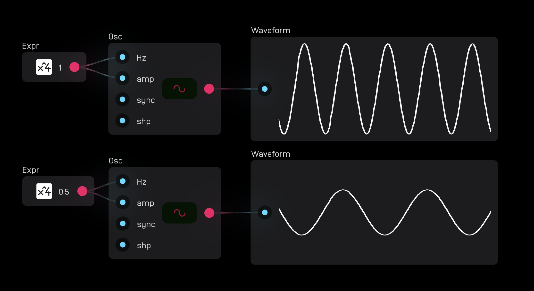
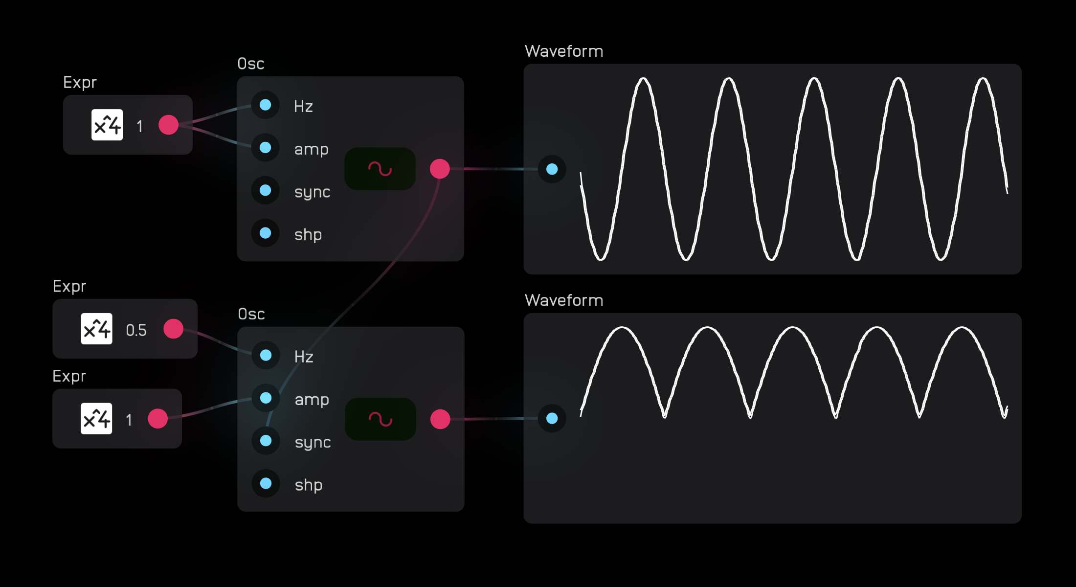
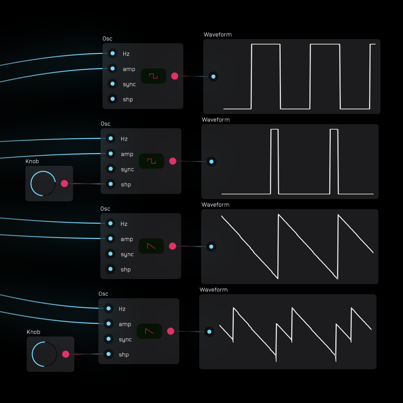
osc
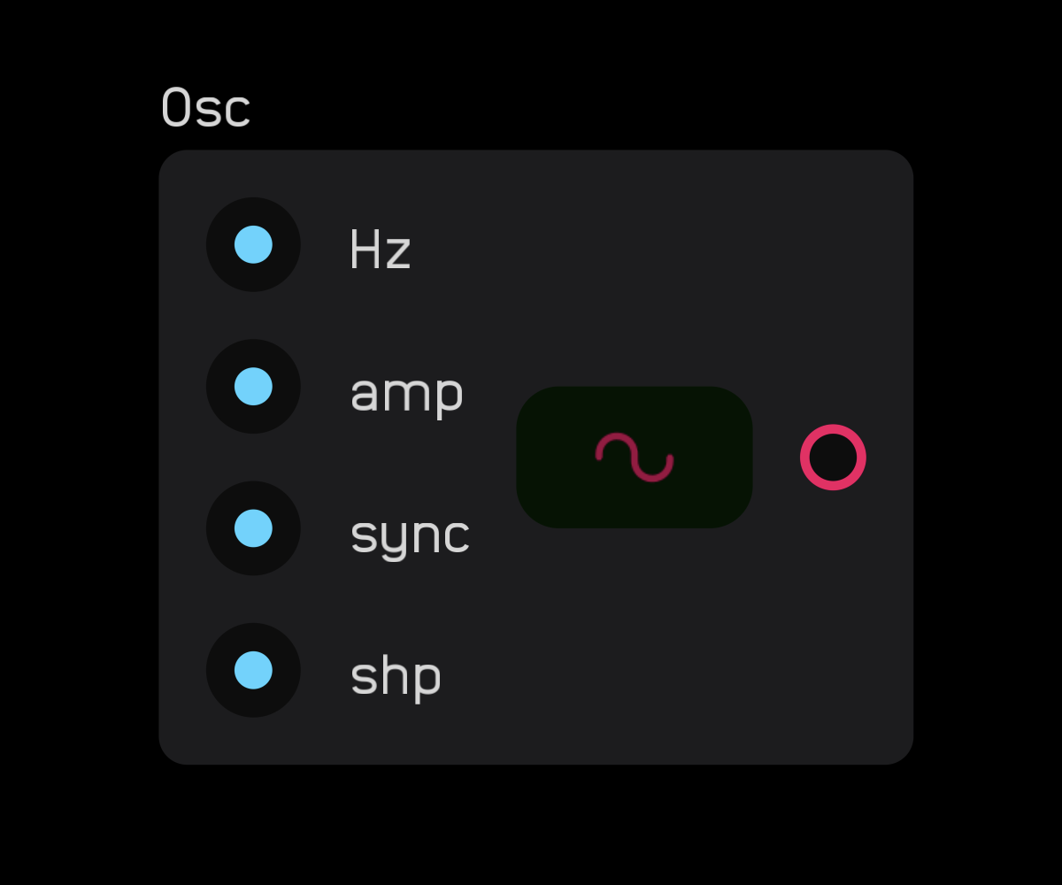
The osc node outputs one of four anti-aliased elemental waveforms as audio: sine, square, triangle, and saw. Select the waveform on the node's panel.
The osc node is intended as an audio-rate oscillator and is band-limited using the miniBLEP method. Using it as an LFO can lead to unpredictable behavior with overshooting caused by the band-limiting.
Inputs:
Hz: Controls oscillator speed from0tosampleRate/2Hzamp: Controls the amplitude of the oscillator waveform.sync: Resets the phase of the waveform on the rising edge of an incoming gate or audio signal (hard sync).shp: Changes waveform shape — for square waves, controls pulse width from 50% to 100%; for saw waves, transforms into a supersaw shape. Modulate this port in the 0 to 1 range.
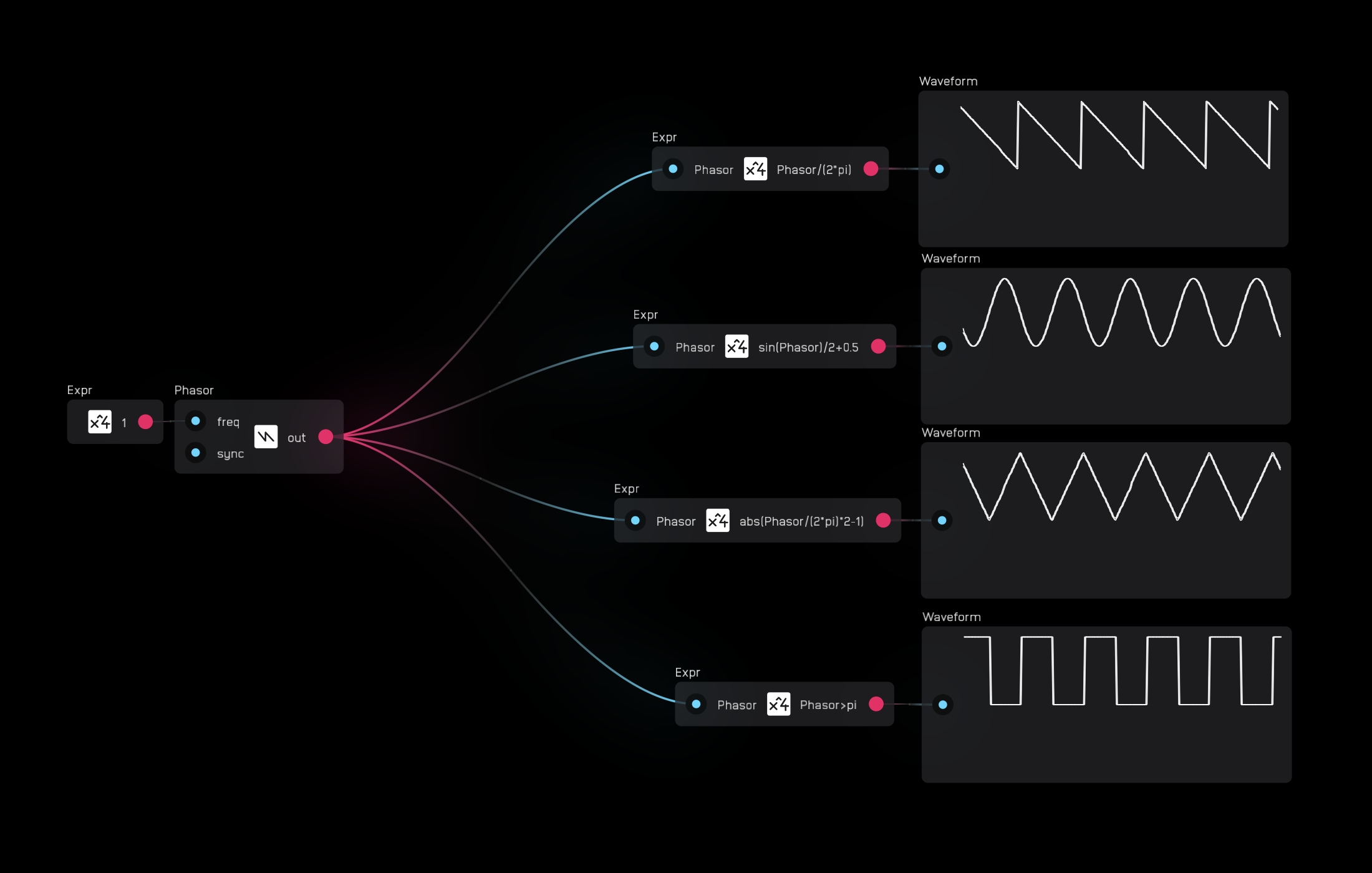
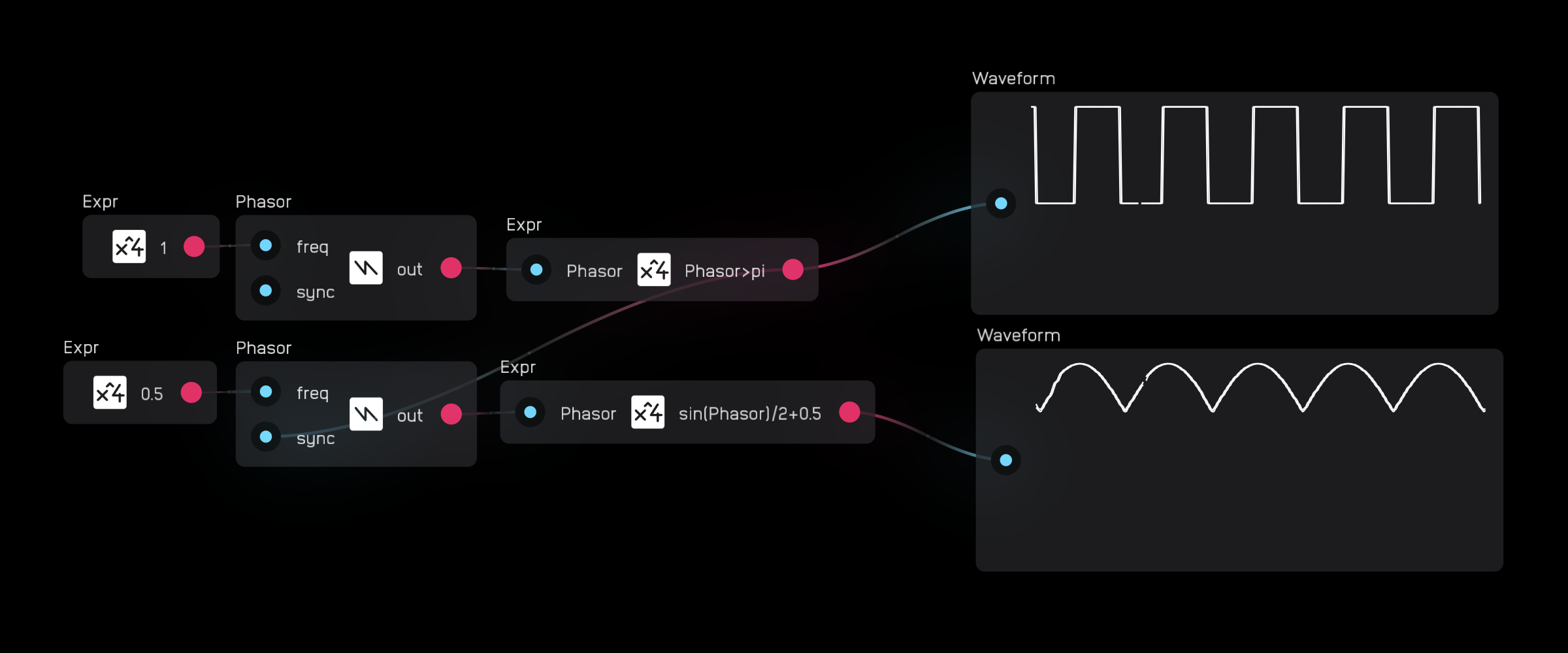
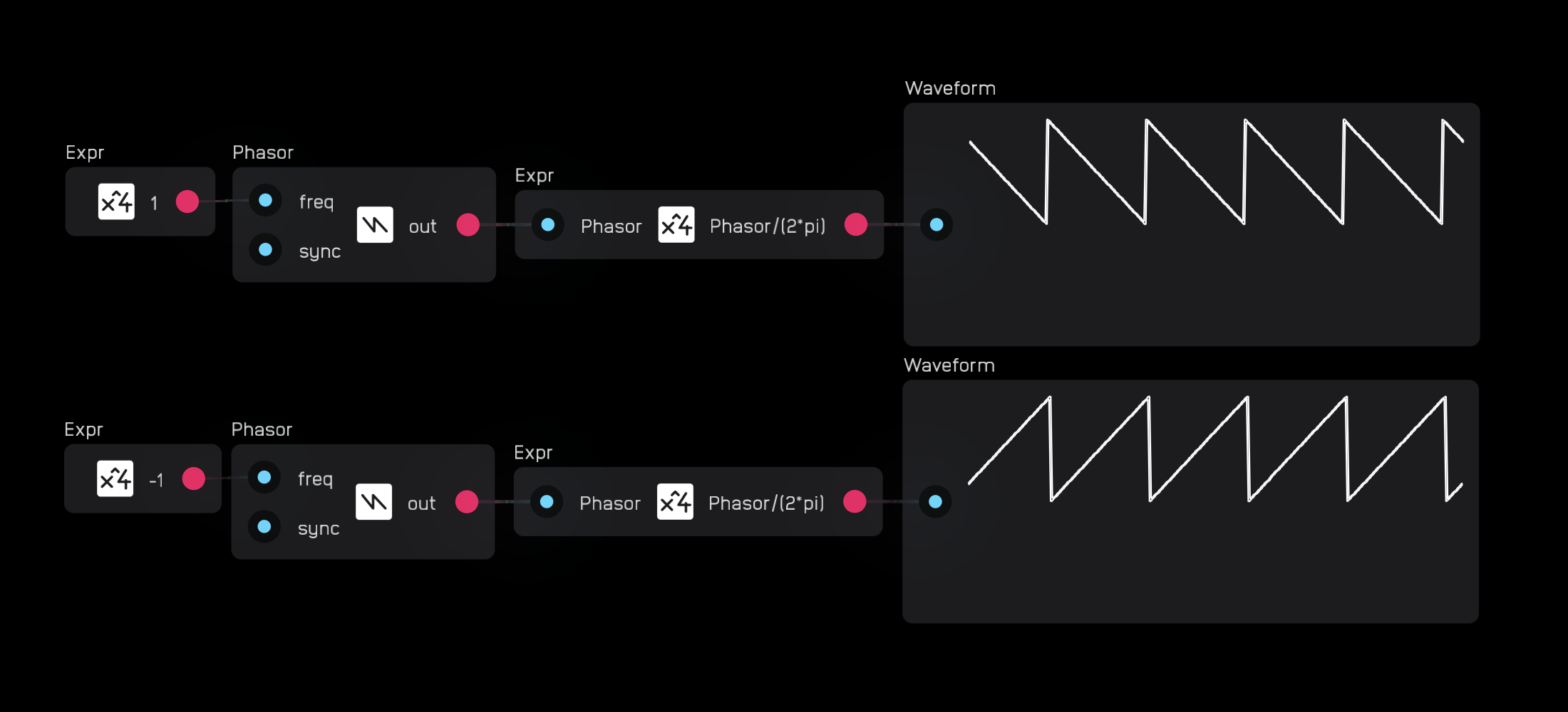
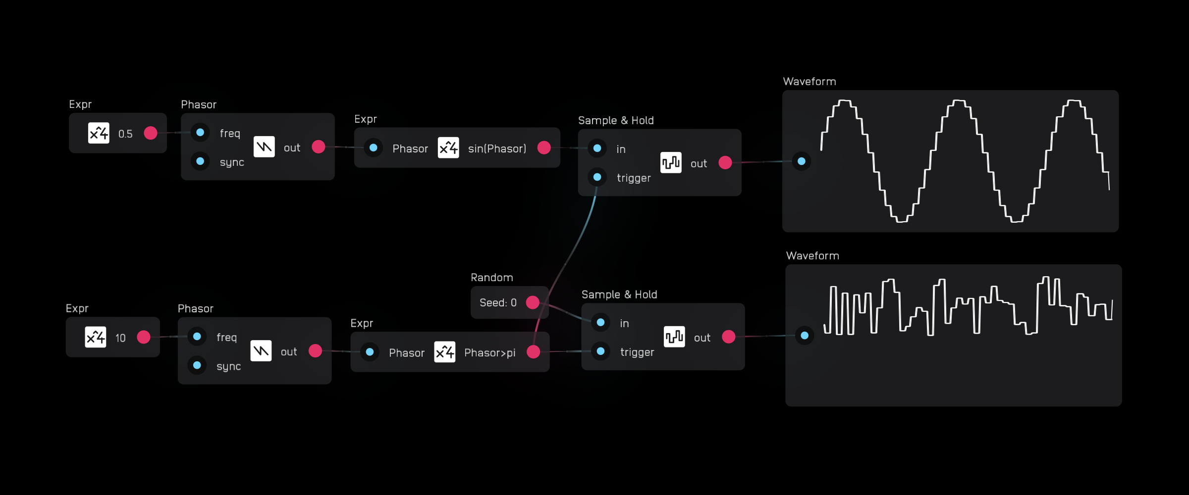
phasor
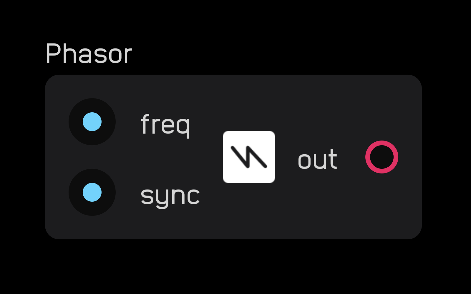
The phasor node outputs a cycling ramp from 0 to 2π with 64-bit internal precision.
A phasor ramp is a tradition timebase for creating cycling waveforms. For example, sin(phasor) outputs a sinewave at the freq rate.
The sync input resets the phasor on the rising edge of a gate or audio signal.
Positive Hz values at the freq input run the phasor from 0 to 2π, while negative Hz values reverse the direction, running from 2π to 0. This bi-directional behavior allows for things like through-zero FM.
sample & hold
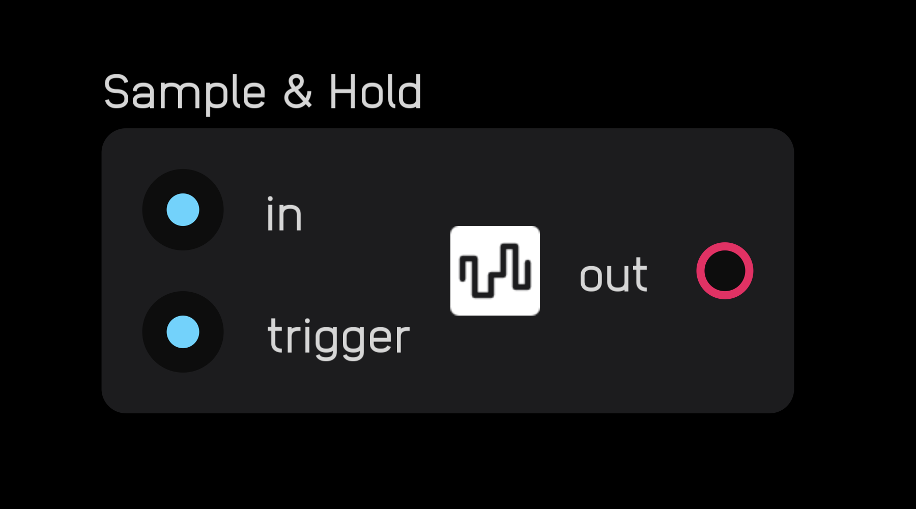
The sample & hold node samples a value at its input on the rising edge of a gate signal at the trigger input and holds that value at its output until triggered again.
Think of it as a single-sample memory node -- select Save Data in the inspector panel to allow the held value to persist across patch saves.
Module Nodes
Module nodes are important elements for creating modules and submodules.
module

The module node lets you encase nodes inside of a UI.
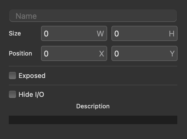
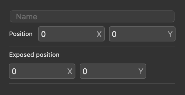
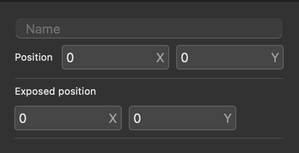
In the inspector panel, you have options to name the module, define its size, whether or not it is exposed, when it is exposed if it should hide its inputs and outputs, and a field to enter a description of what it does.
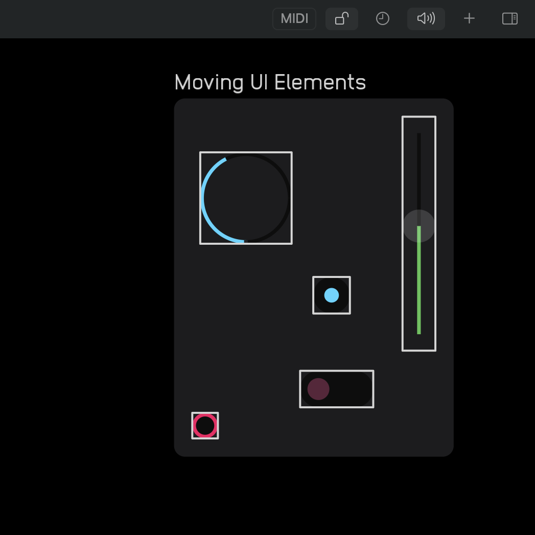
Exposed elements within a module node will appear automatically on the UI. You can move them around by clicking or tapping the lock icon to enter Edit Modules mode.
There are two classes of things you can create with the module nodes: modules and submodules.
The difference between them is that modules are meant to be interacted with while submodules are like custom nodes used to create modules.
input
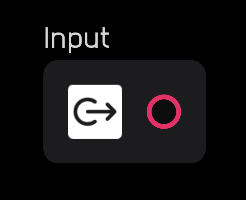
The input node brings signals into a module node. It must be placed inside the module node.
It can be renamed in the inspector panel.
output
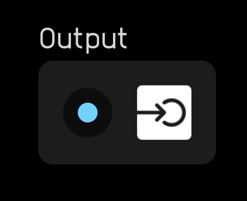
The output node sends signals out of a module node. It must be placed inside the module node.
It can be renamed in the inspector panel.
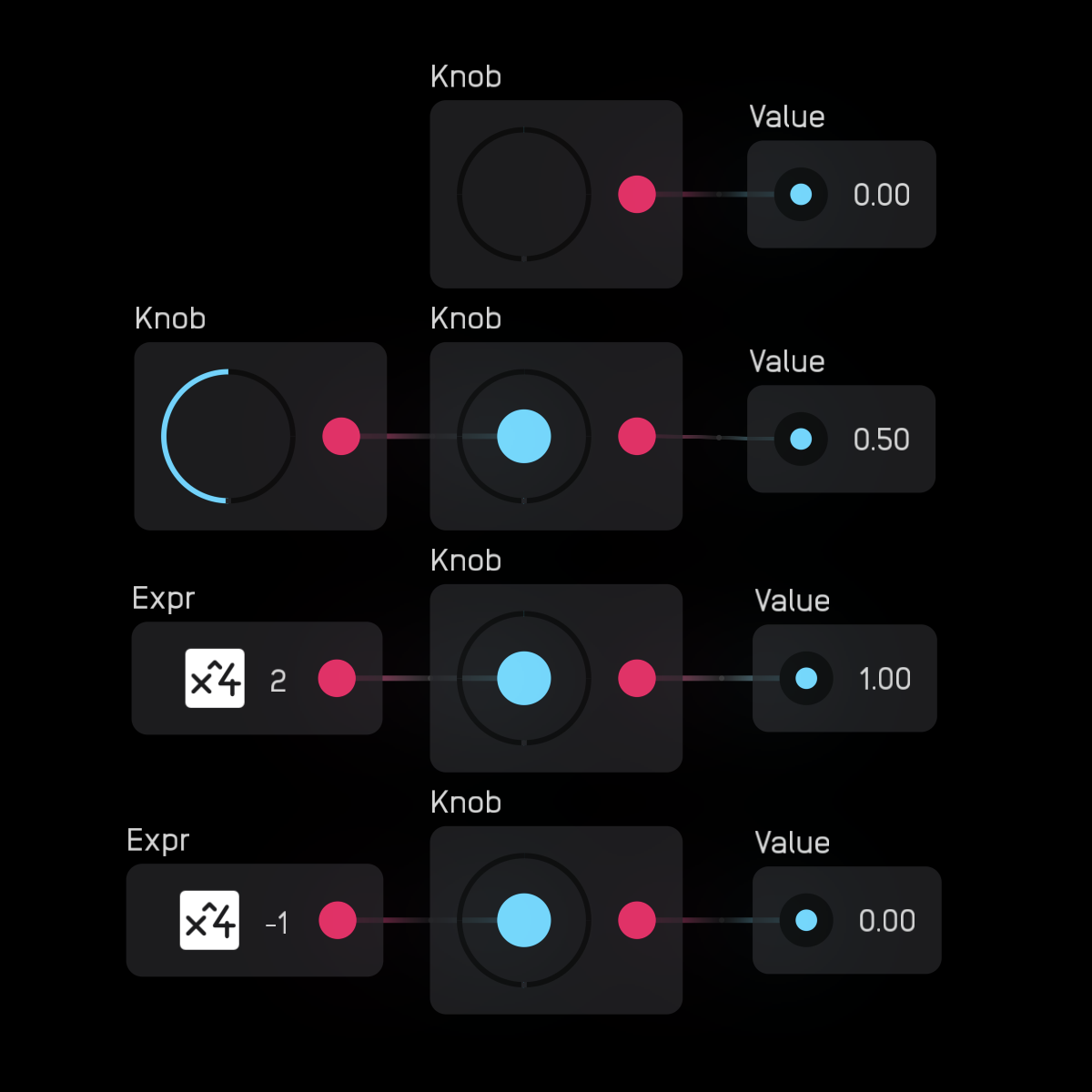
knob
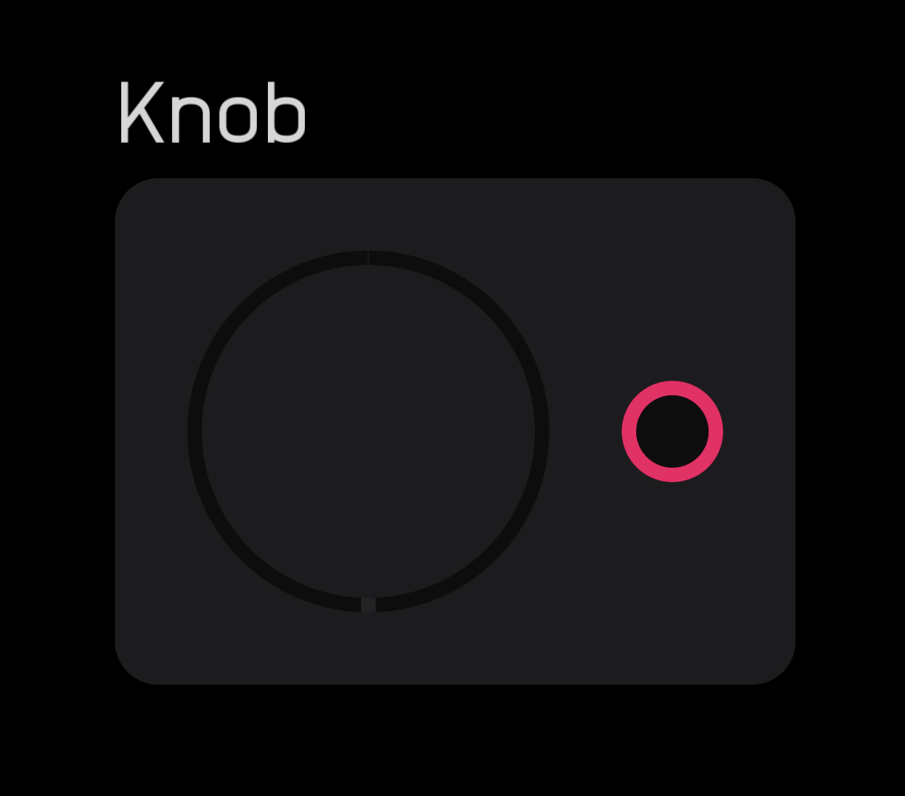
The knob node modifies other nodes and outputs a 0 to 1 mod signal. This signal can be scaled and shaped by expr, mapper, and spline nodes.
In the inspector panel, directly set the Value, change the Style, Icon, color, and MIDI CC and Channel.
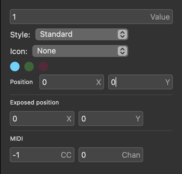
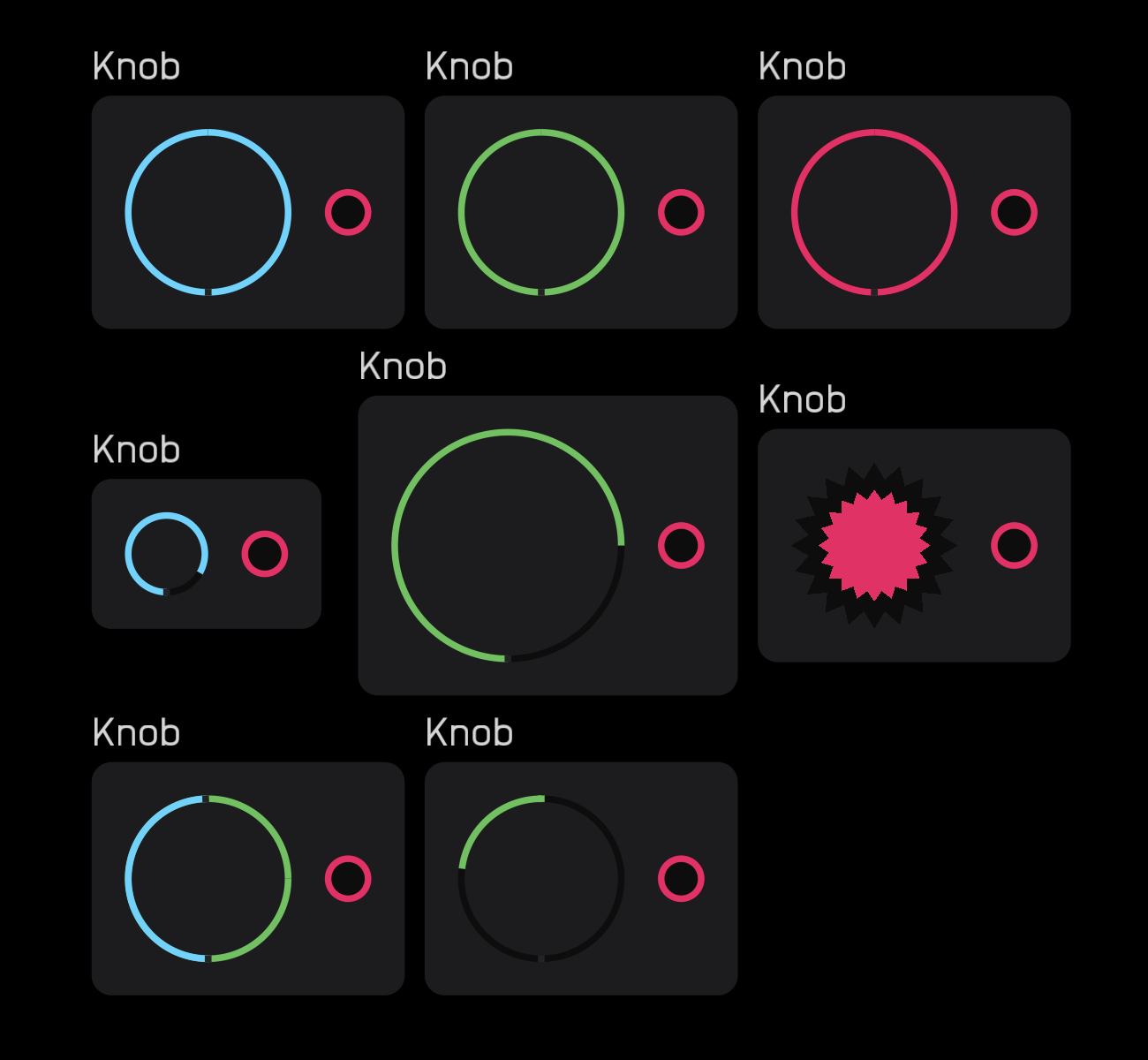
Wires can be attached directly to knobs. When attached, a blue circle appears at the center. The input signal is clamped to the 0 to 1 mod signal range.
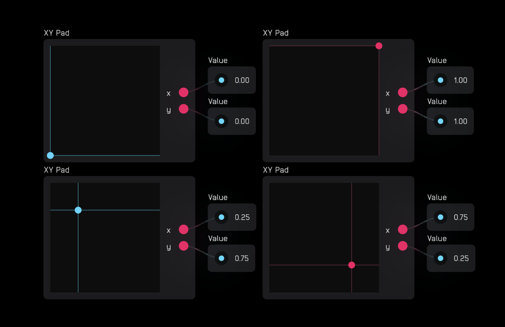
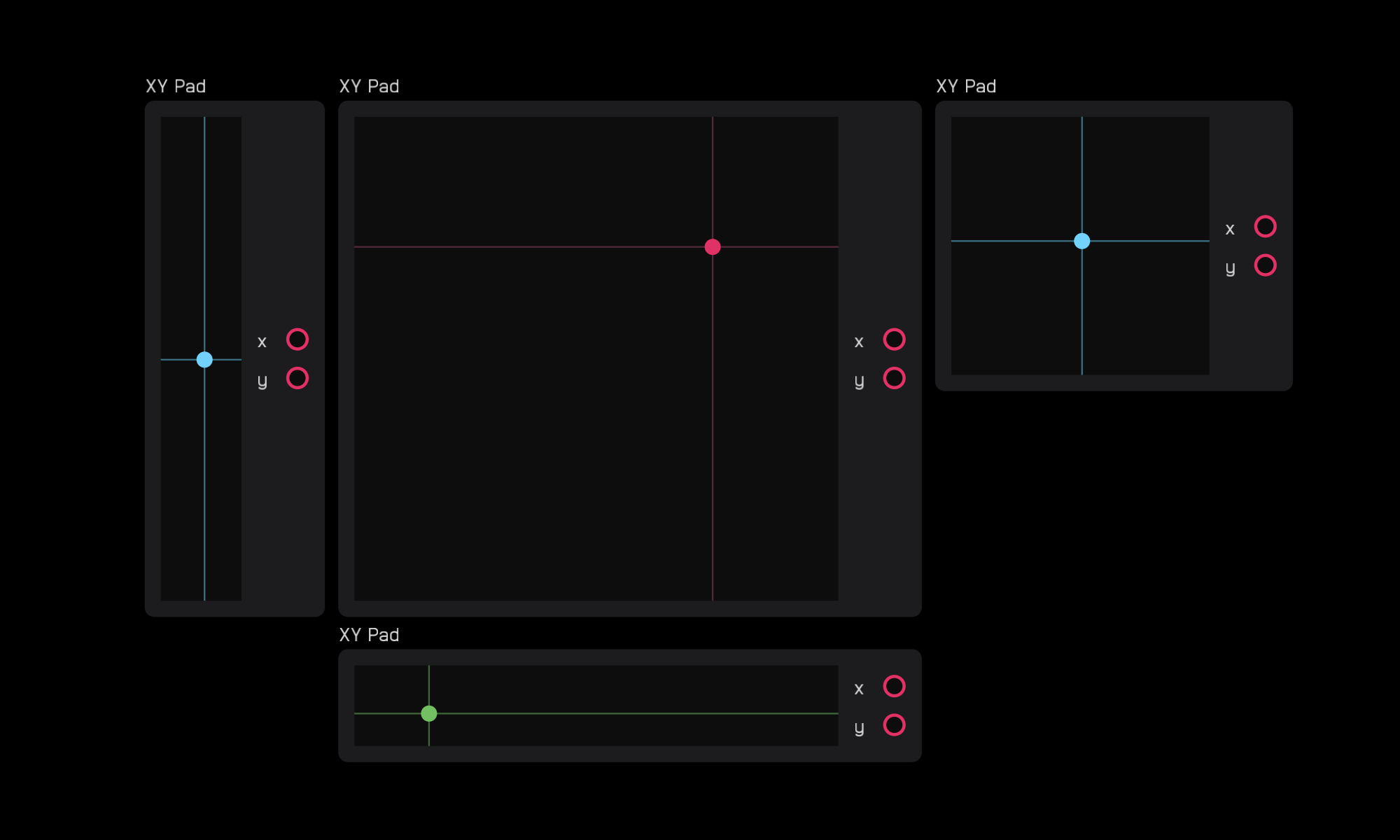
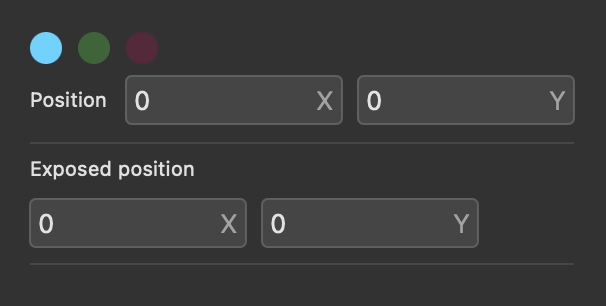
xy pad
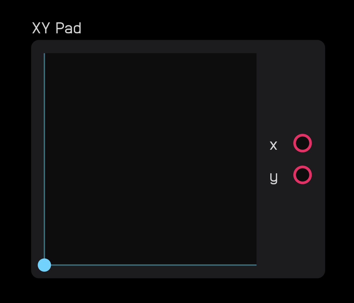
The xy pad node outputs two mod signals that correspond to the (x, y) coordinates of where you click or touch. This point is marked by a colored dot.
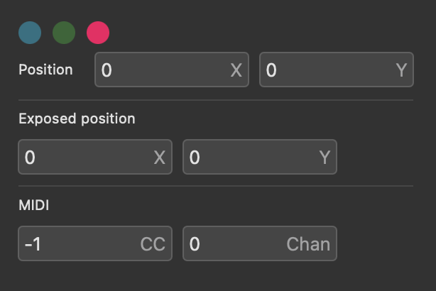
In the inspector panel you can change the Size of the node and its color.
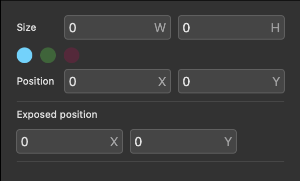
You can make the node smaller, larger, or rectangular.
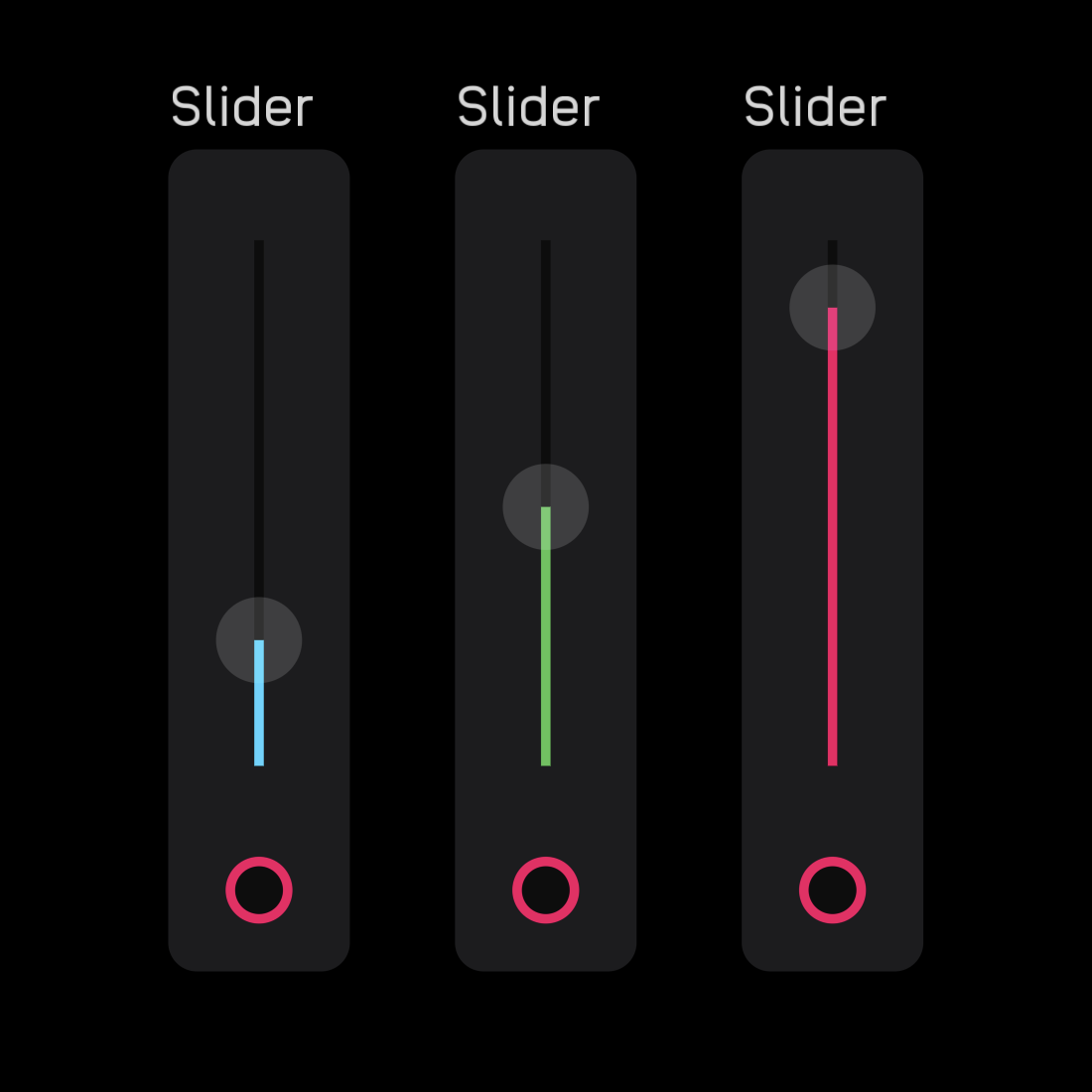
slider
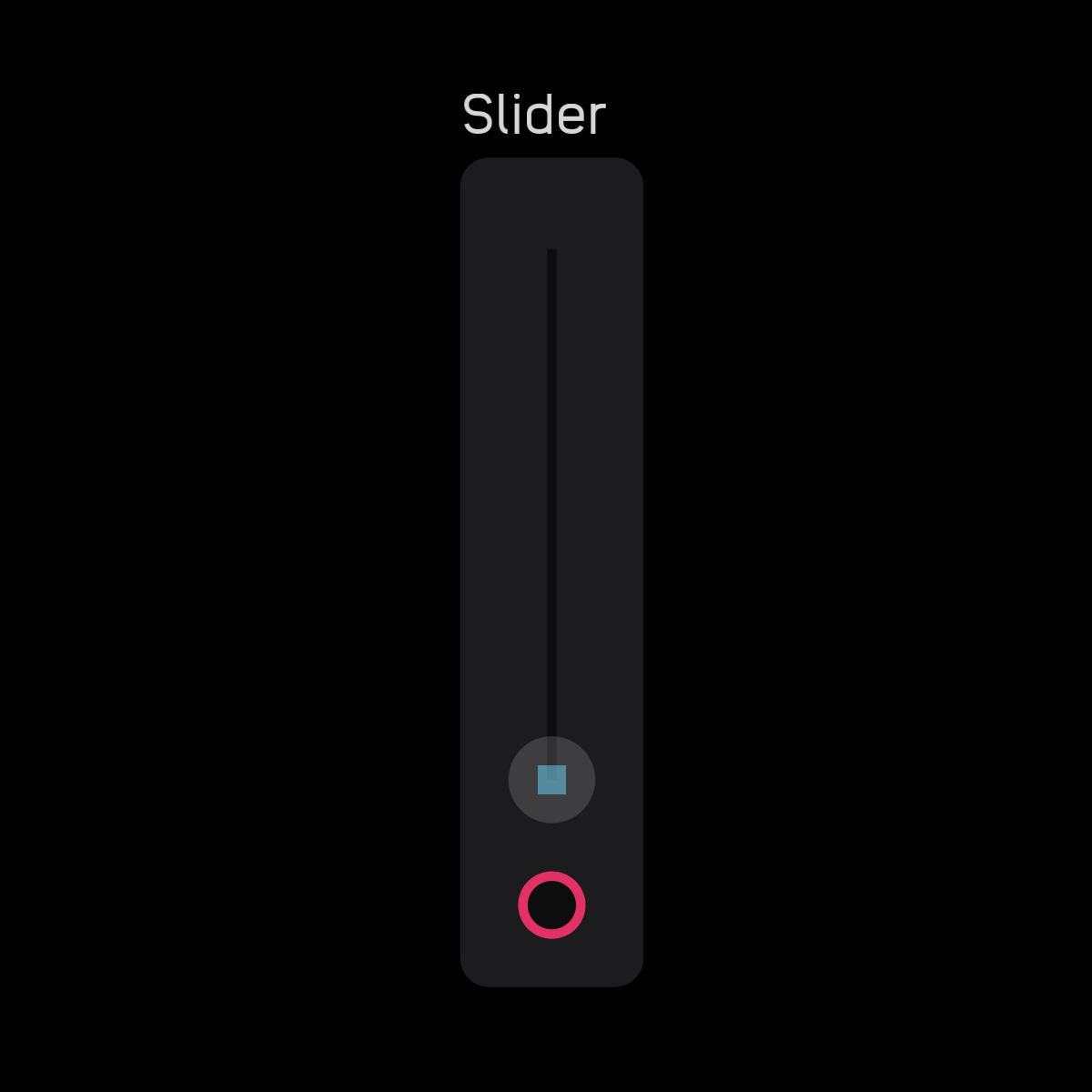
The slider node is used to modify other nodes. It outputs a 0 to 1 mod signal. This signal can be scaled and shaped by expr, mapper, and spline nodes.
When the slider node is zeroed (turned all the way down) a square appears in the center of the small circle.
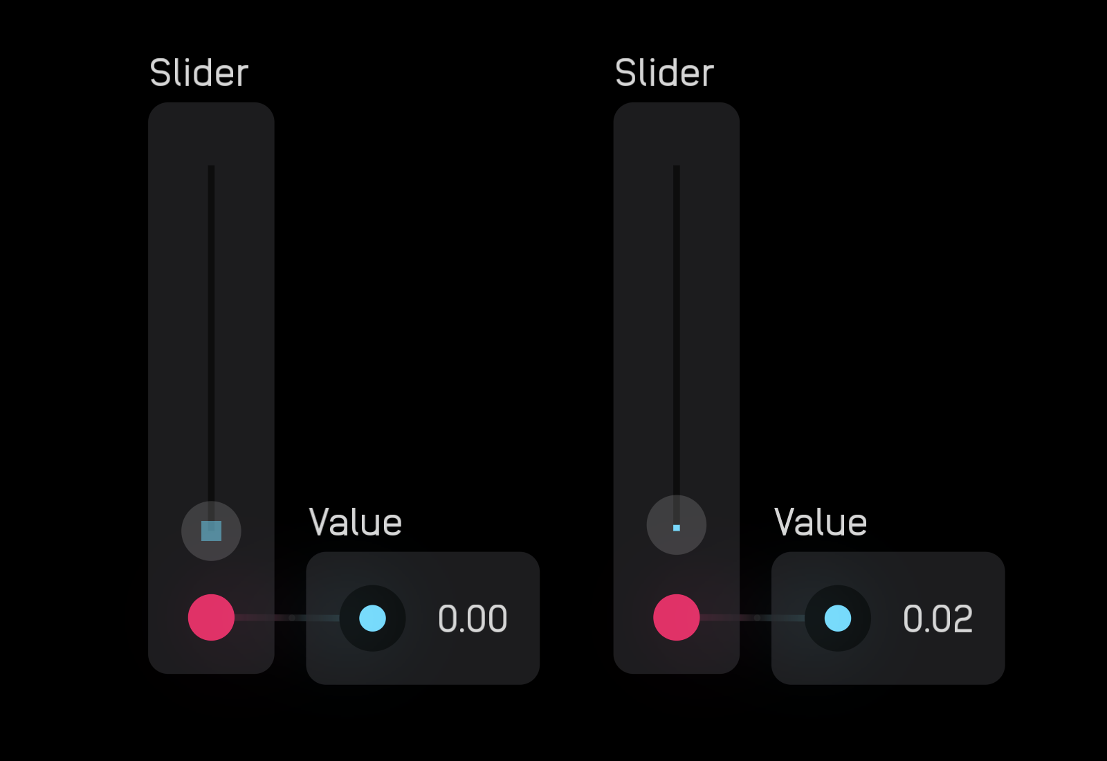
In the inspector panel you can change the color of the slider to blue, green, or red, and assign MIDI CC and Channel.
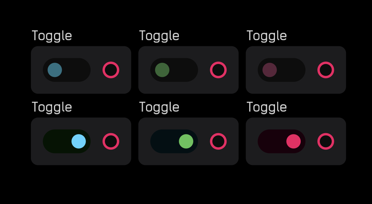
toggle
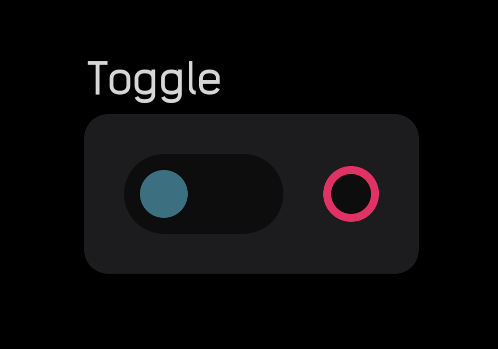
The toggle node outputs a 0 or 1 gate signal. When the switch is set to the left, the output is 0, and when it's set to the right, it is 1.
In the inspector panel you can set the color of the switch as blue, green, or red.
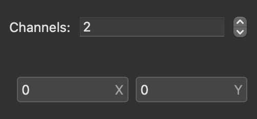
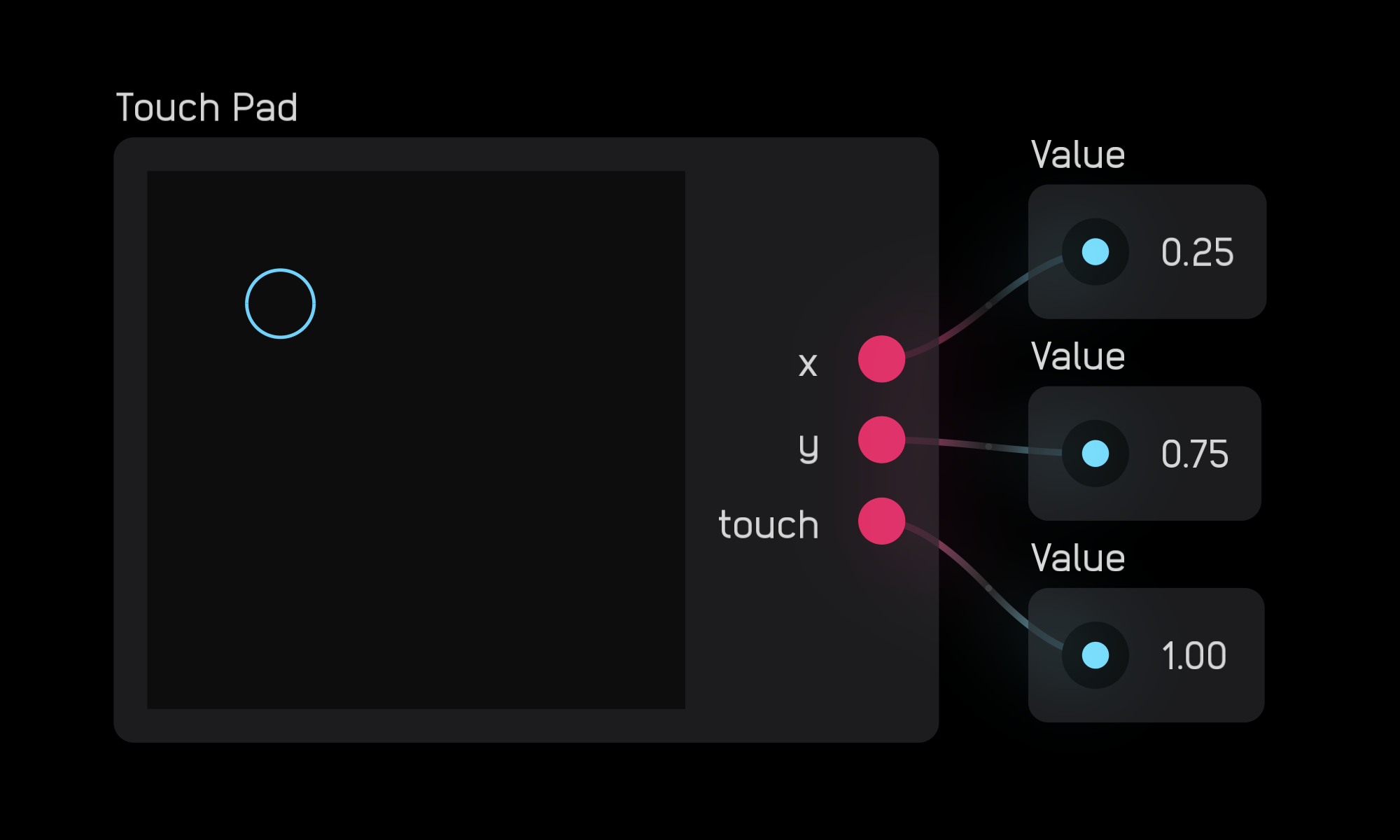
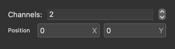
touch pad
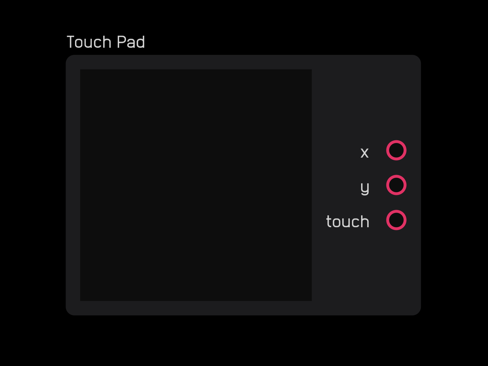
The touch pad node outputs two mod signals that correspond to the (x, y) coordinates of where you click or touch. This point is marked by a blue circle.
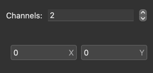
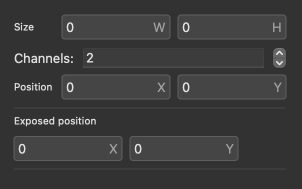
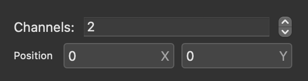
In the inspector panel you can change the Size of the node and the number of Channels (for iOS multitouch).
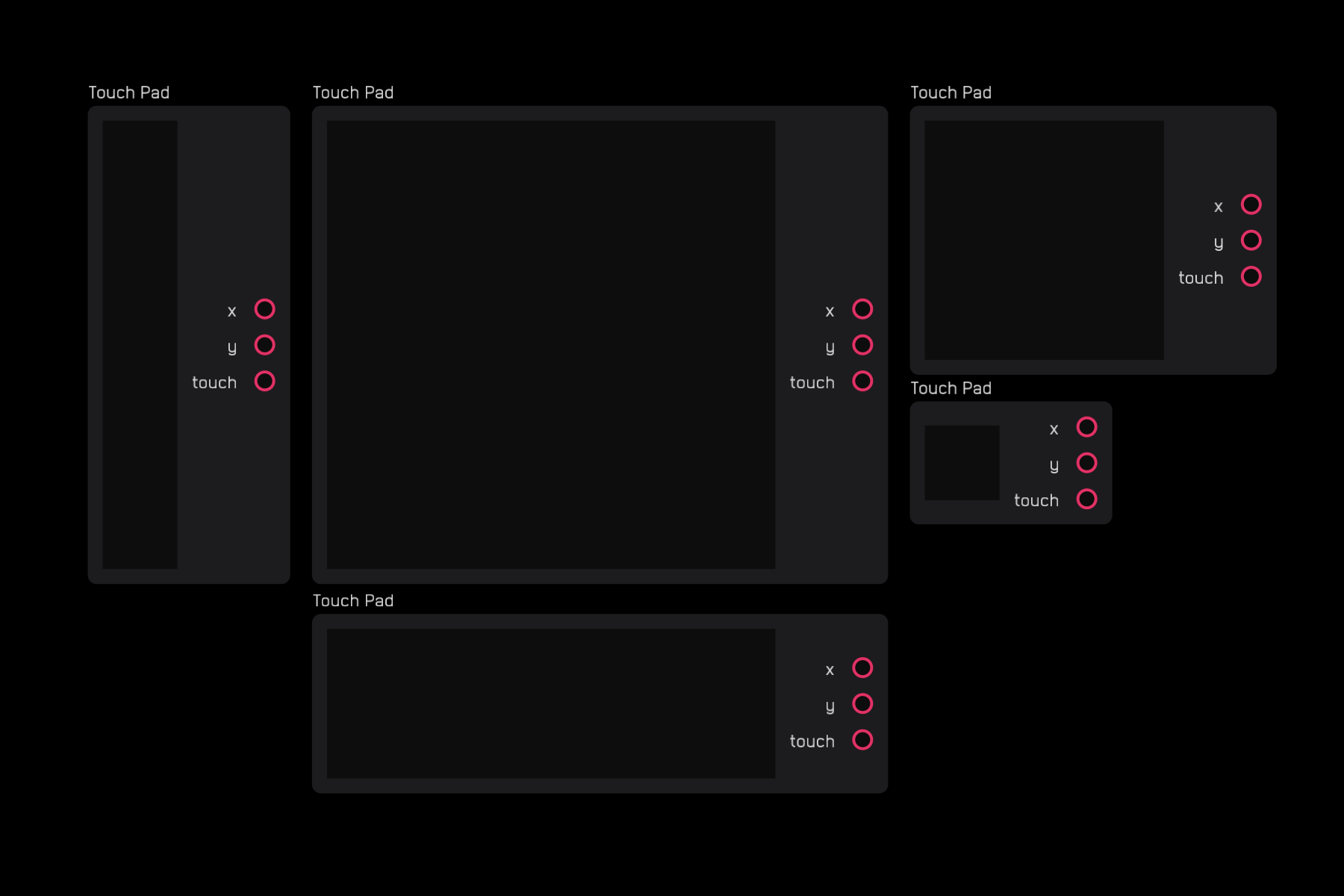
You can make the node smaller, larger, or rectangular.
Poly Nodes
Poly nodes create and manage polyphonic signals.
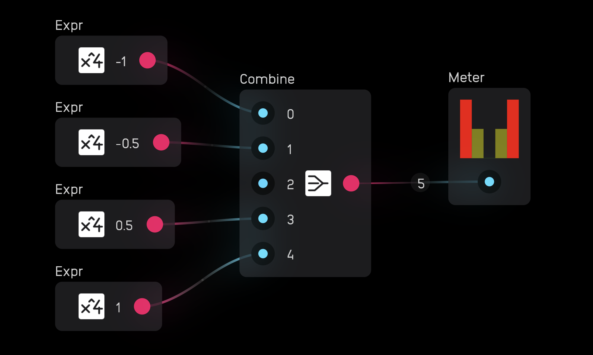
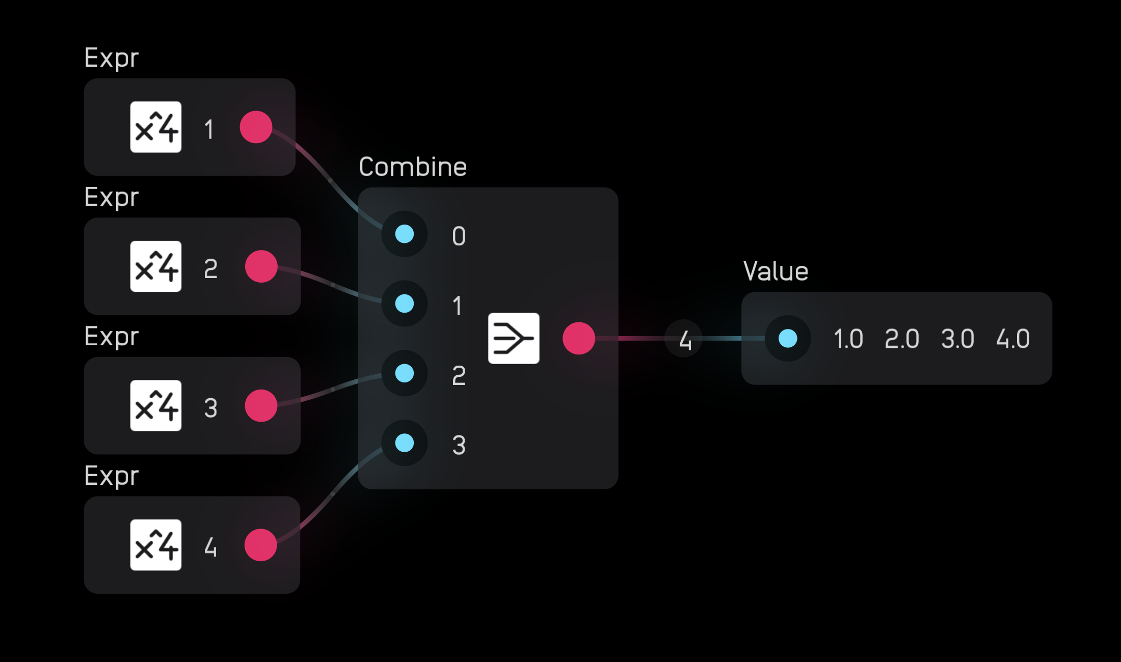
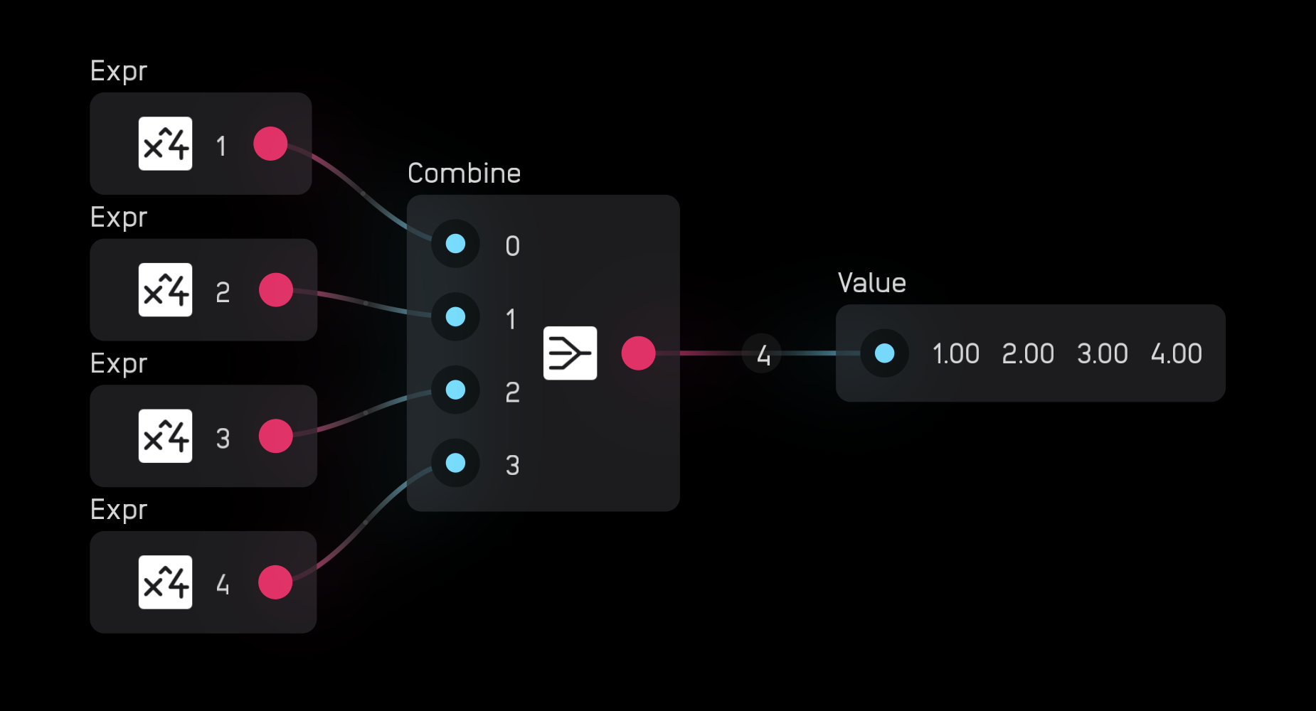
combine
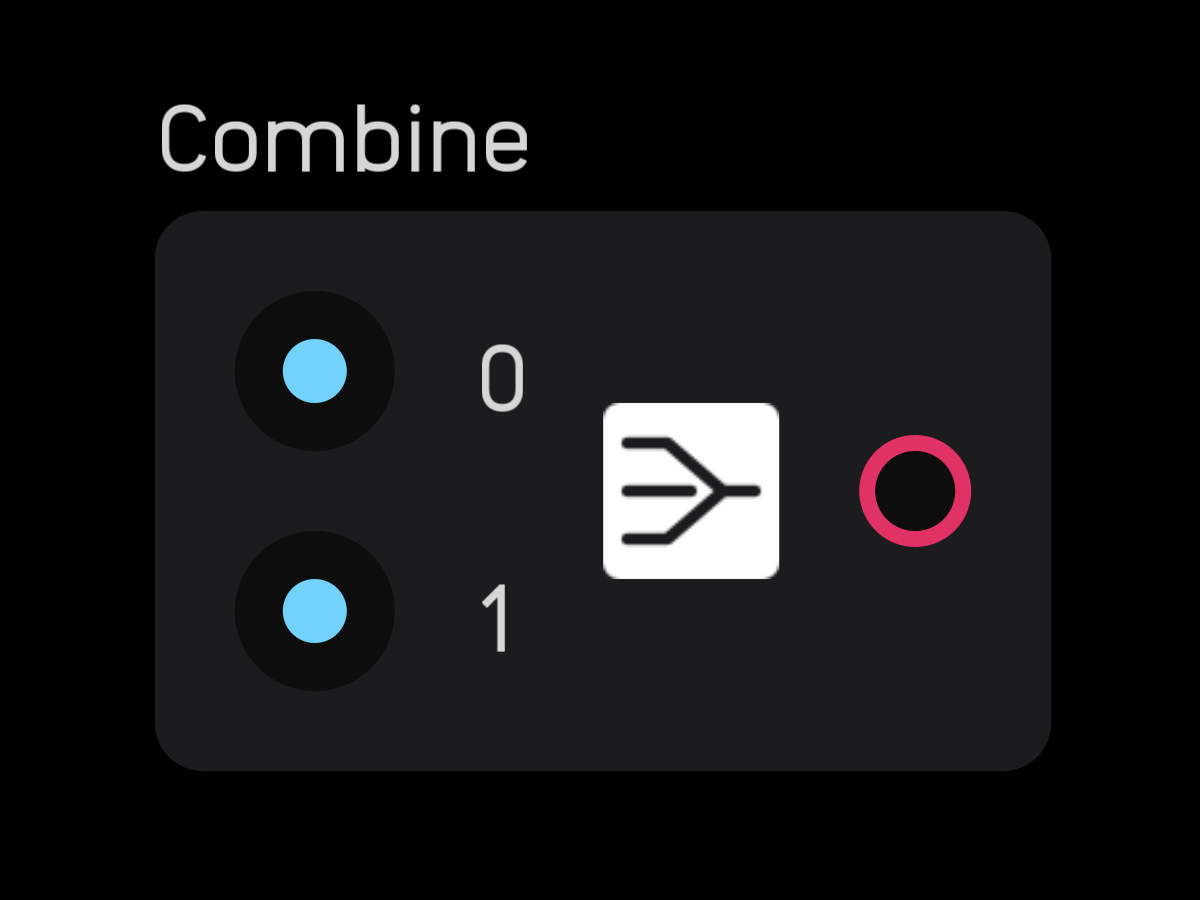
The combine node takes 2 to 256 mono signals and combines them into one polyphonic signal.
In the inspector panel, set the number of channels.
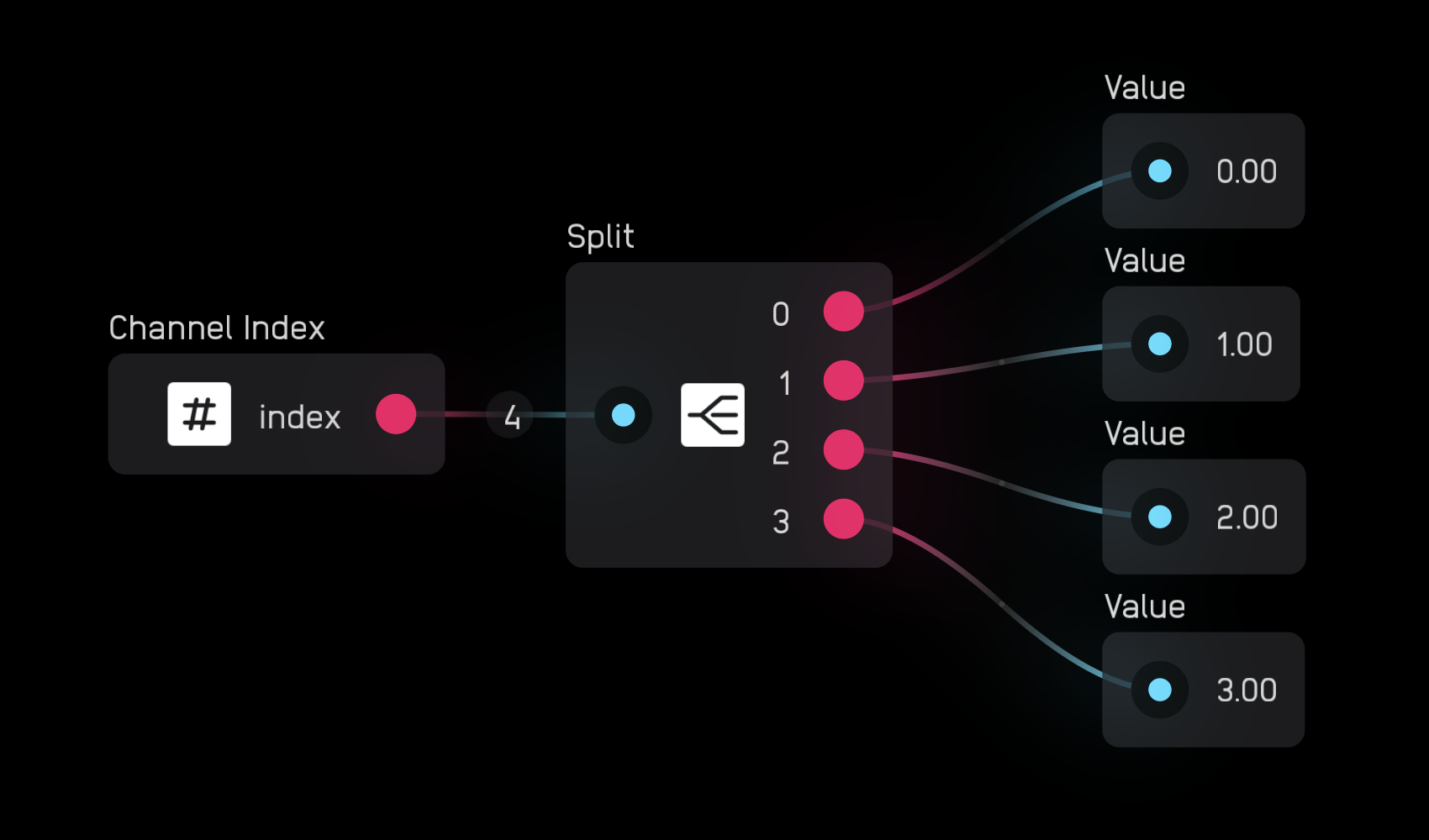
split
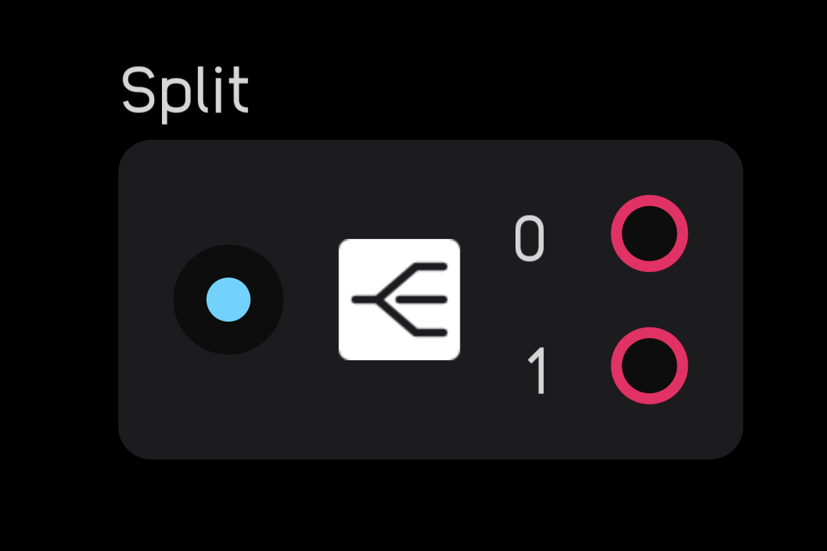
The split node takes a poly signal and splits it into 1 to 256 mono signals.
In the inspector panel, set the number of channels.
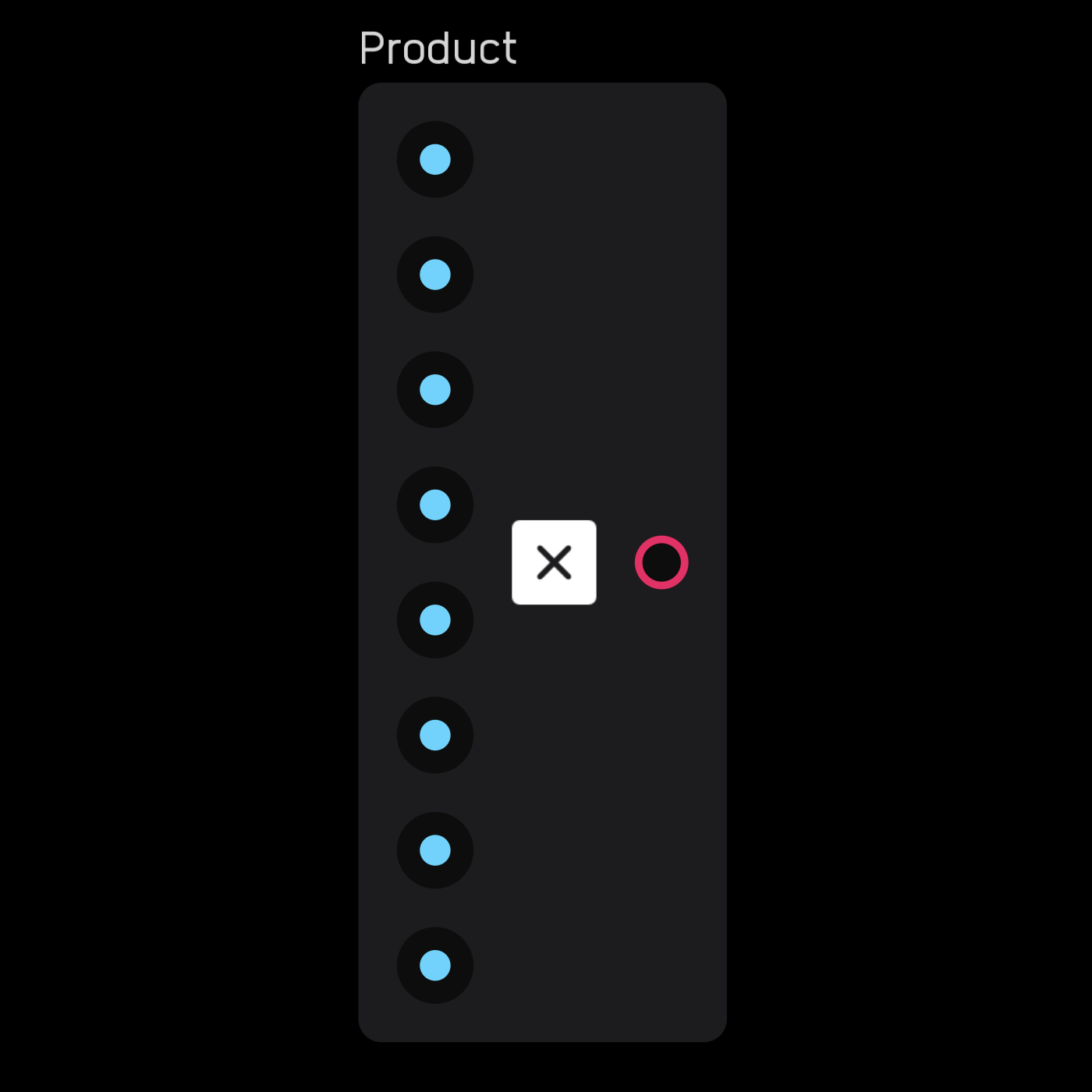
poly mix
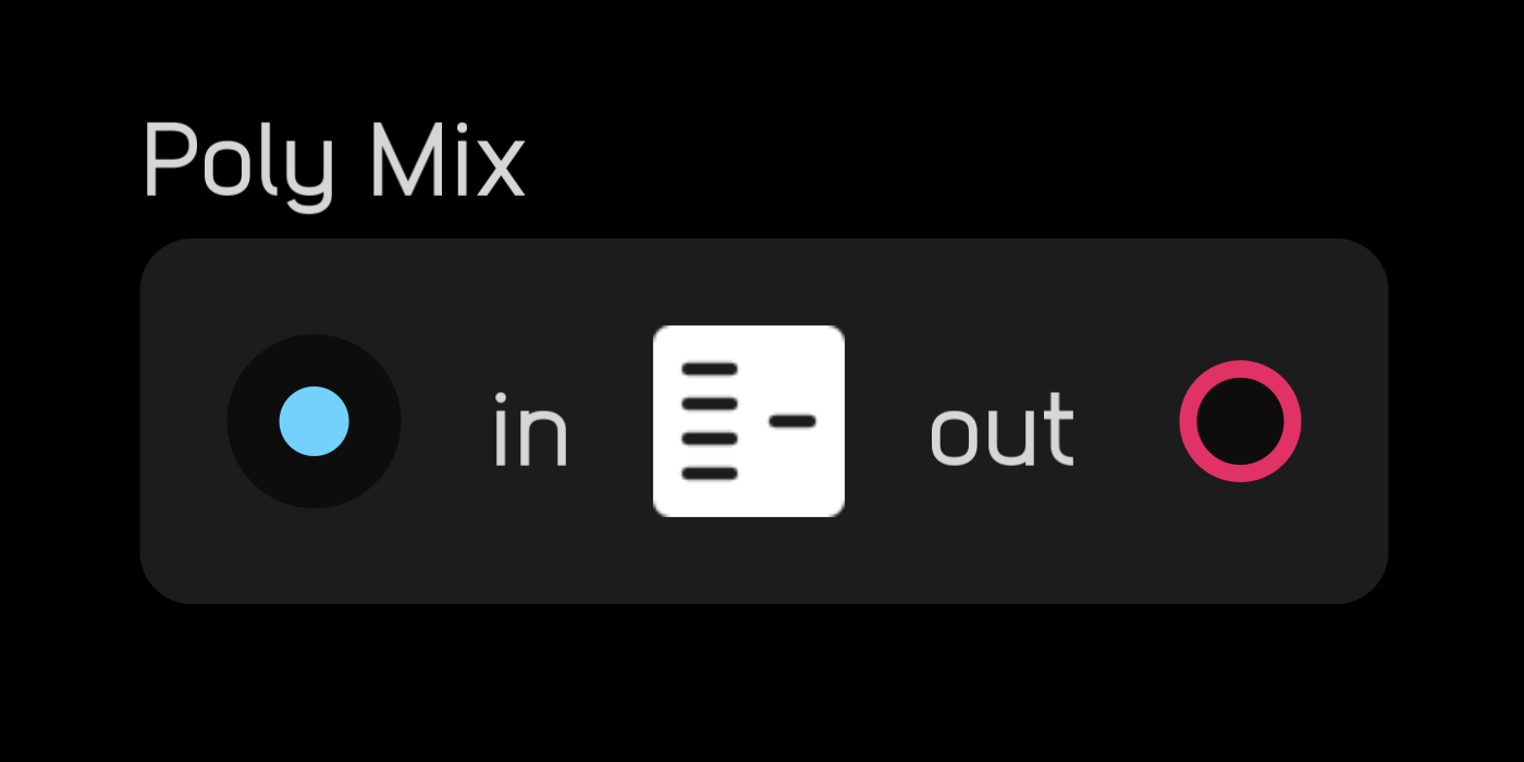
The poly mix node takes a poly signal and mixes it down to a mono signal.
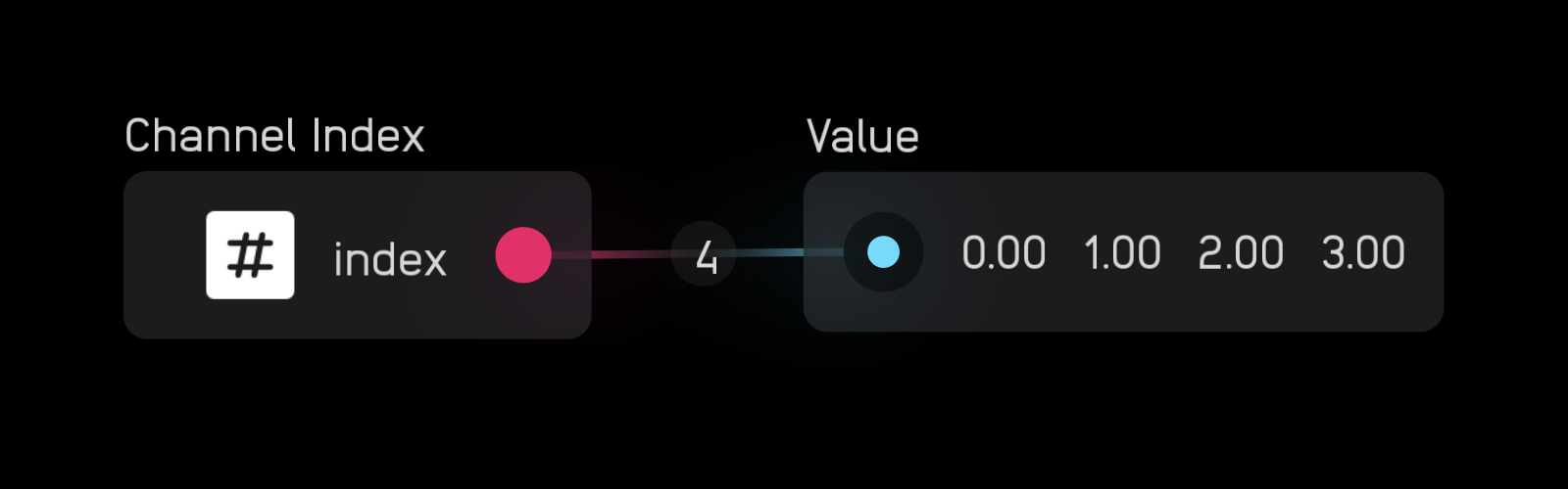
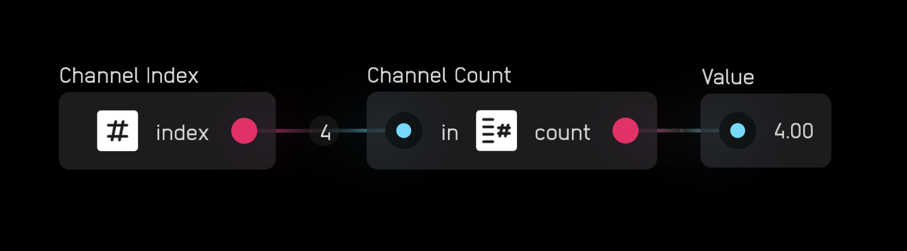
channel index
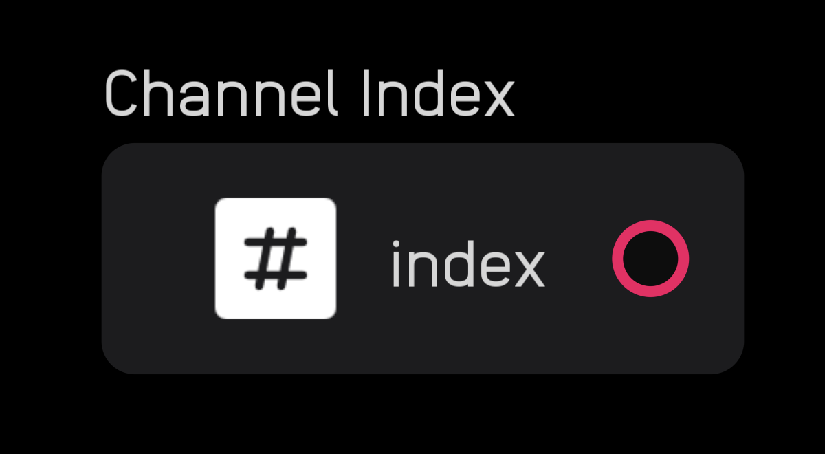
The channel index node creates a signal with 1 to 256 channels, where each channel is an integer index number indexed from 0.
channel count
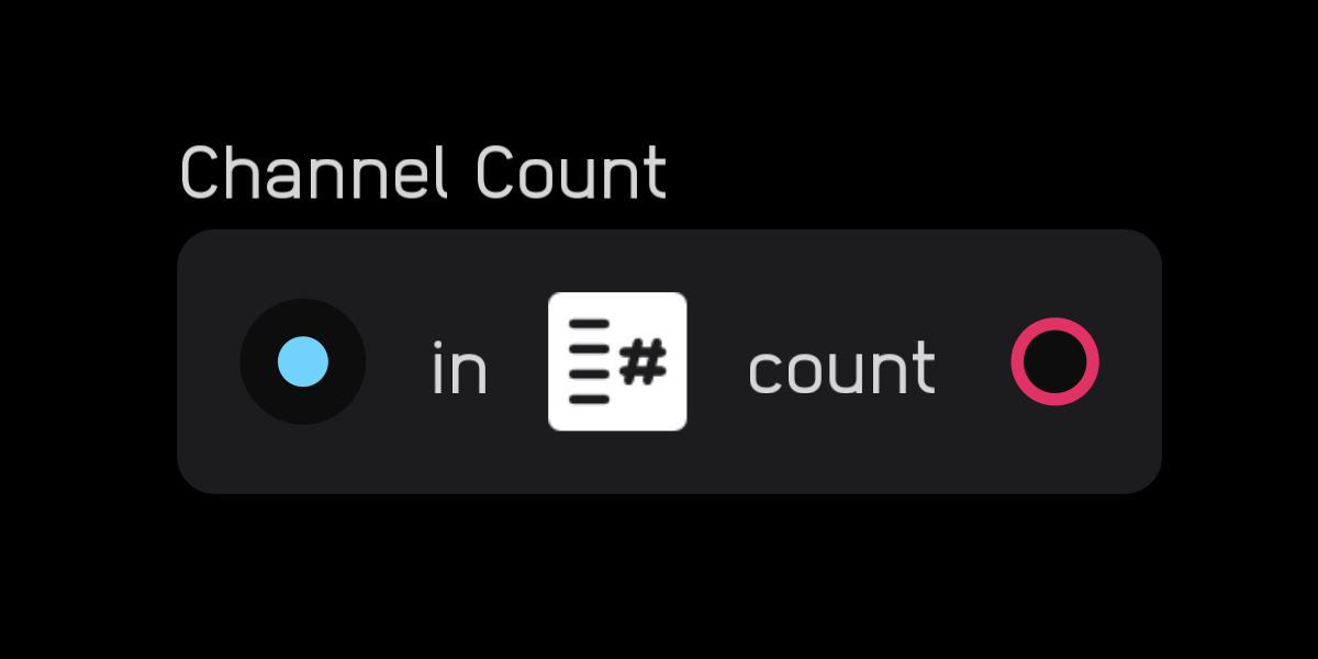
The channel count node outputs the number of channels in a signal as an integer.
Switch Nodes
Switch nodes route signals and control signal flow.
mux
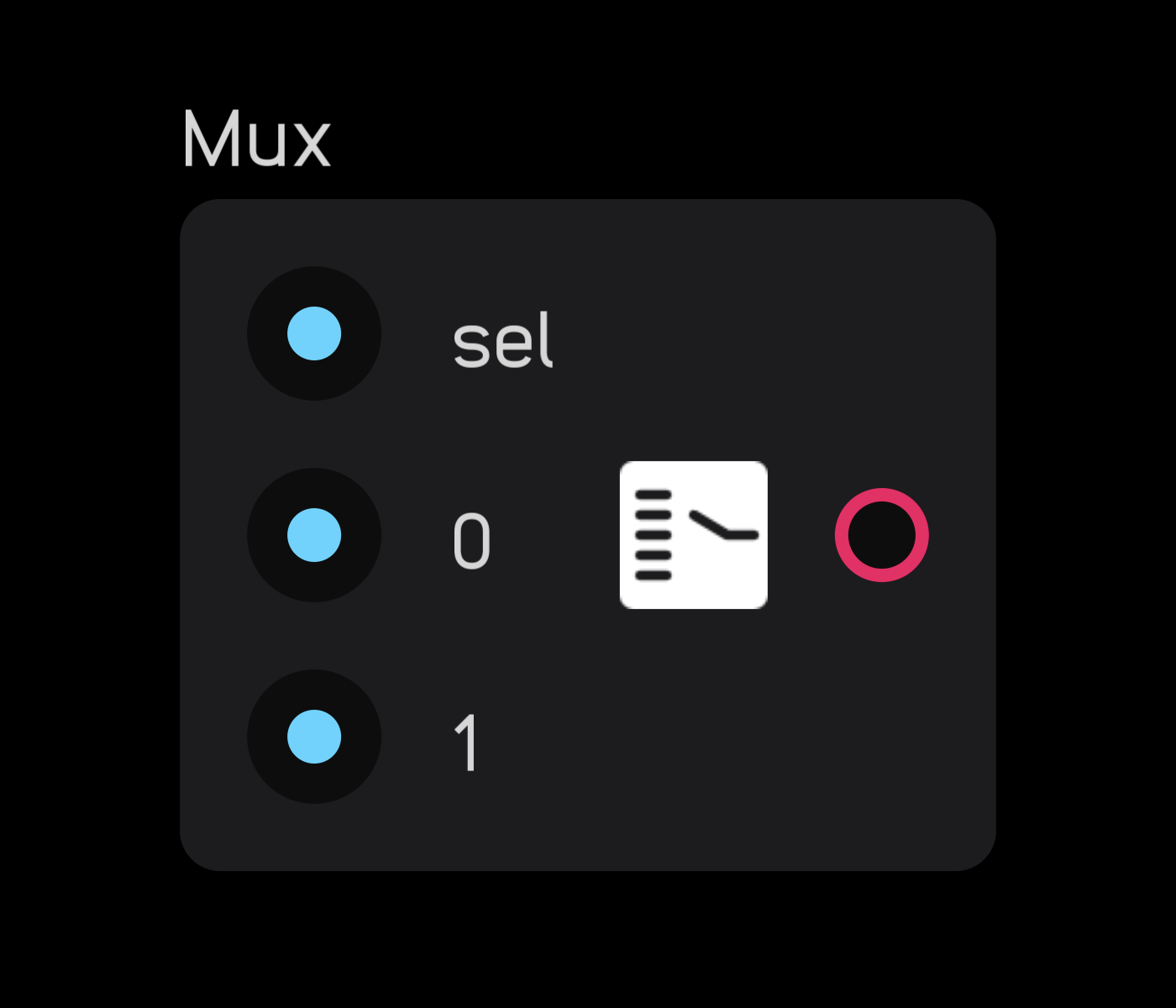
The mux node routes one of 2 to 256 inputs to a single output according to the sel value, which is indexed from 0.
In the inspector panel, set the number of inputs.

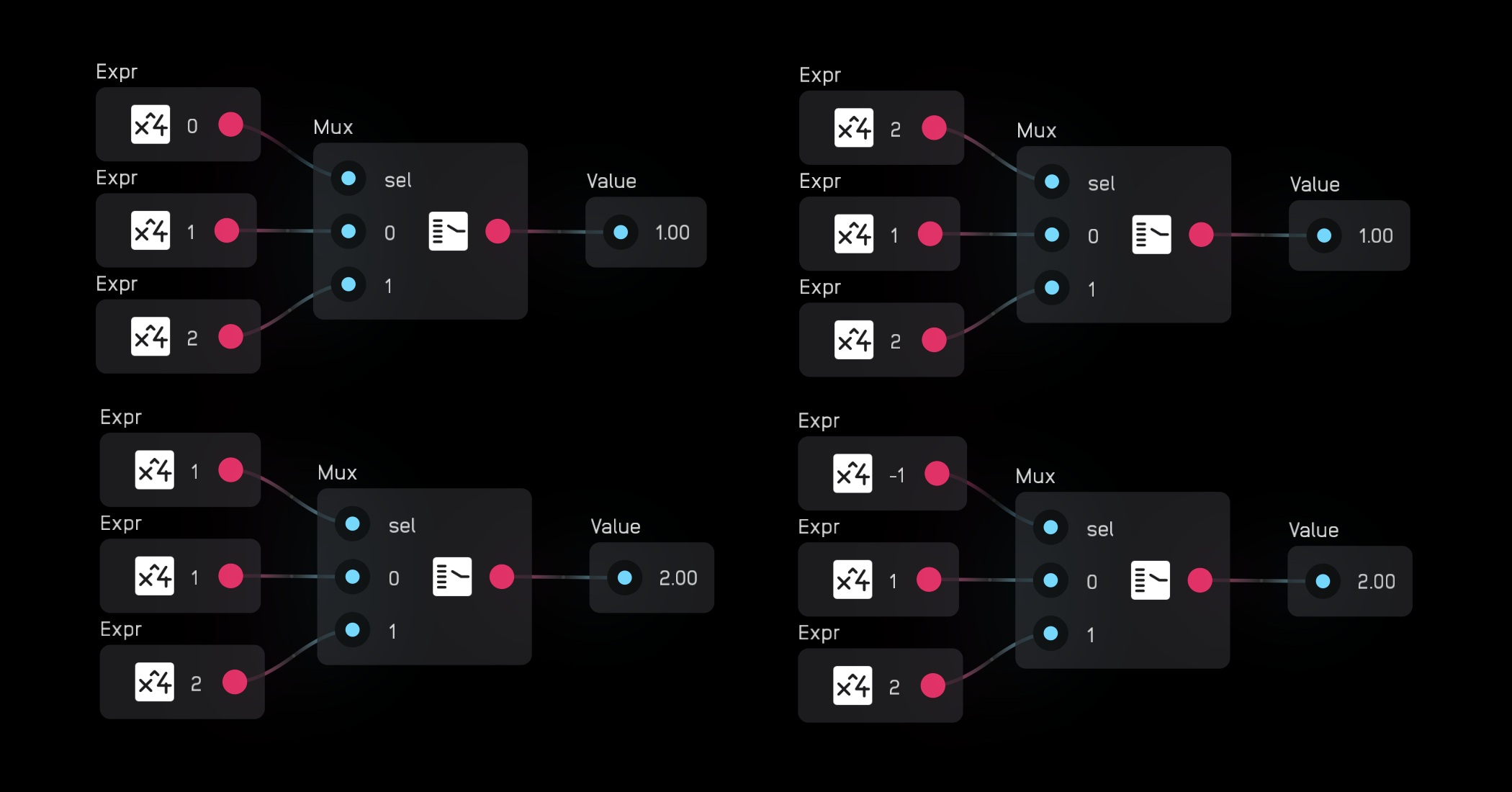
When the sel value is ≥ 0 but < 1, the 0 input is sent to the output. When sel is ≥ 1 but < 2, the 1 input is sent to the output, and so on.
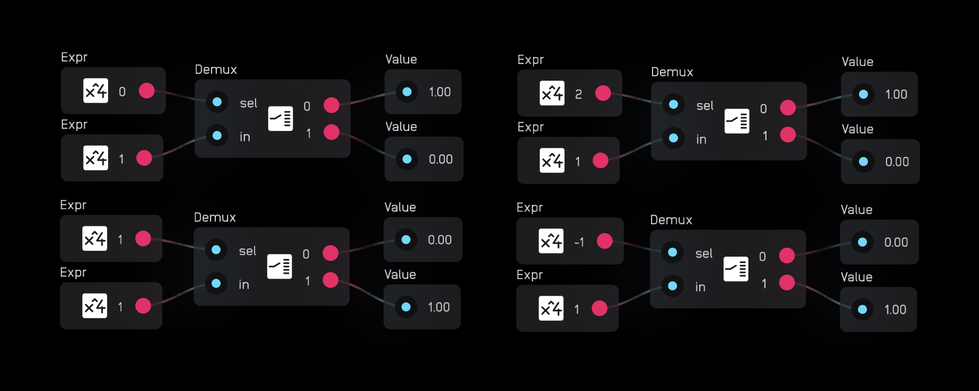
demux
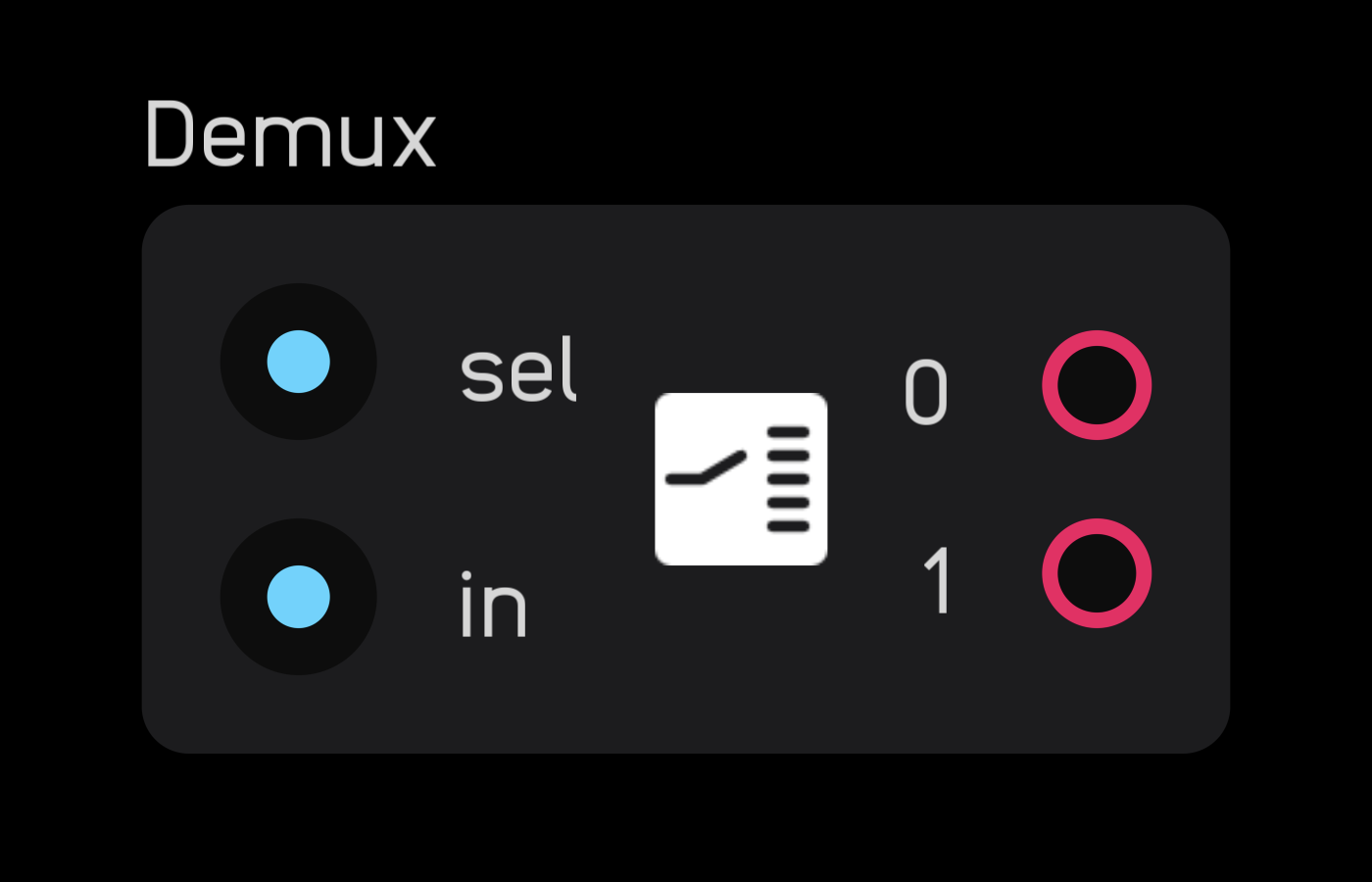
The demux node routes one signal to 2 to 256 outputs according to the sel value, which is indexed from 0.
In the inspector panel, set the number of outputs.
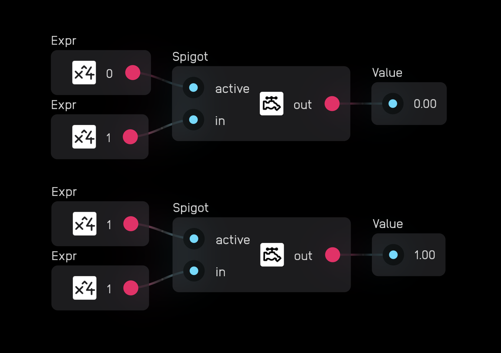
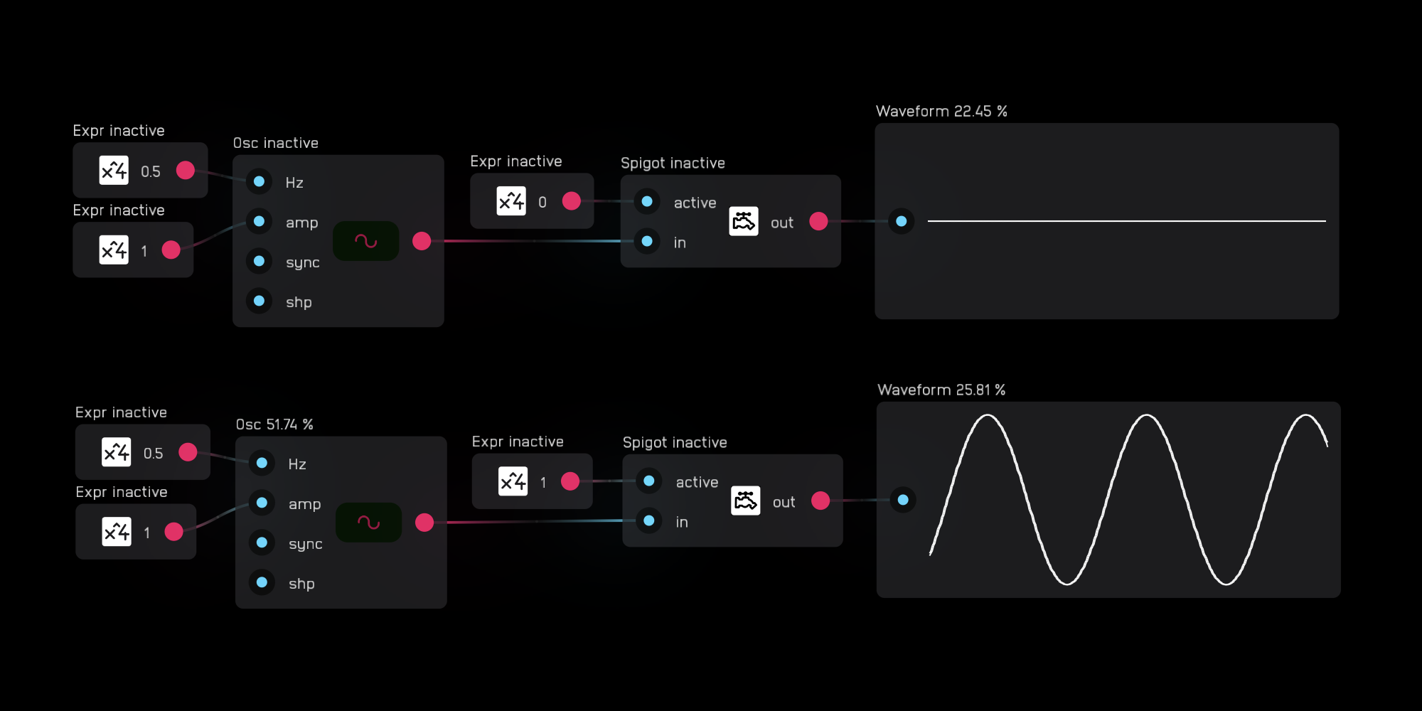
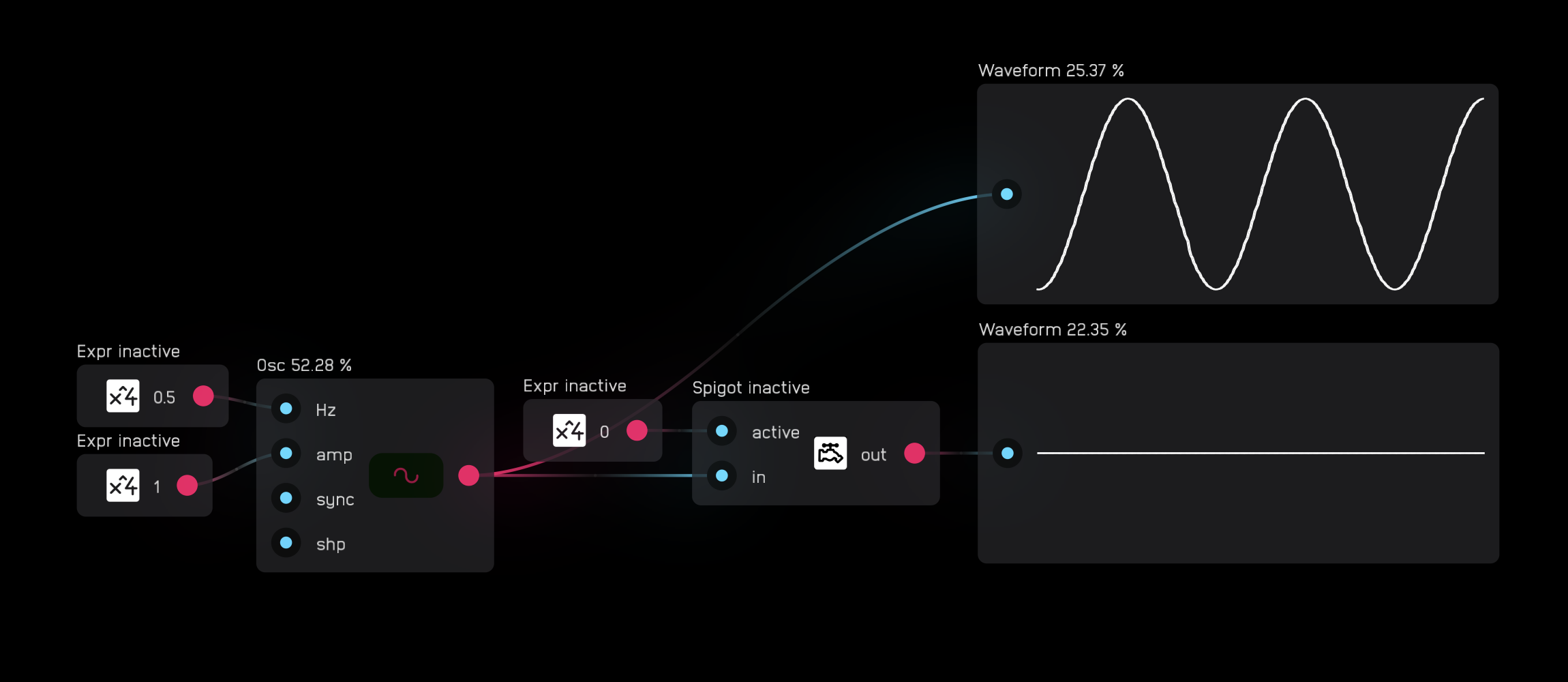
spigot
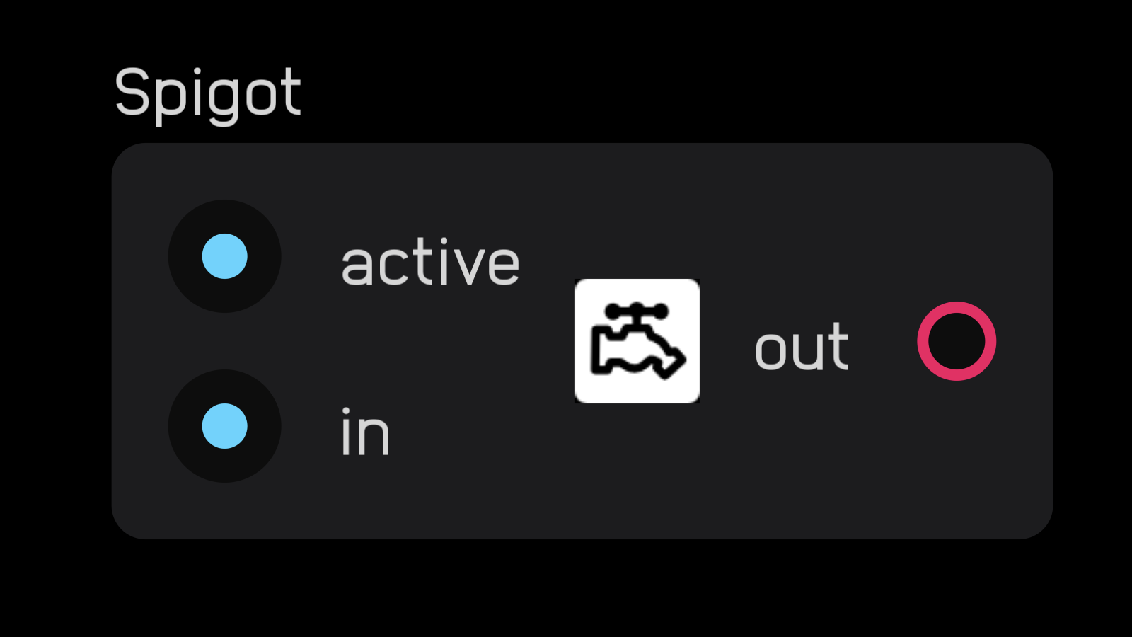
The spigot node turns off processing for all nodes to its left in the signal path that aren't connected to an output node like a meter or dac.
When the active input is 0, nothing passes and processing is halted. When the active input is high, the signal passes and everything processes normally.
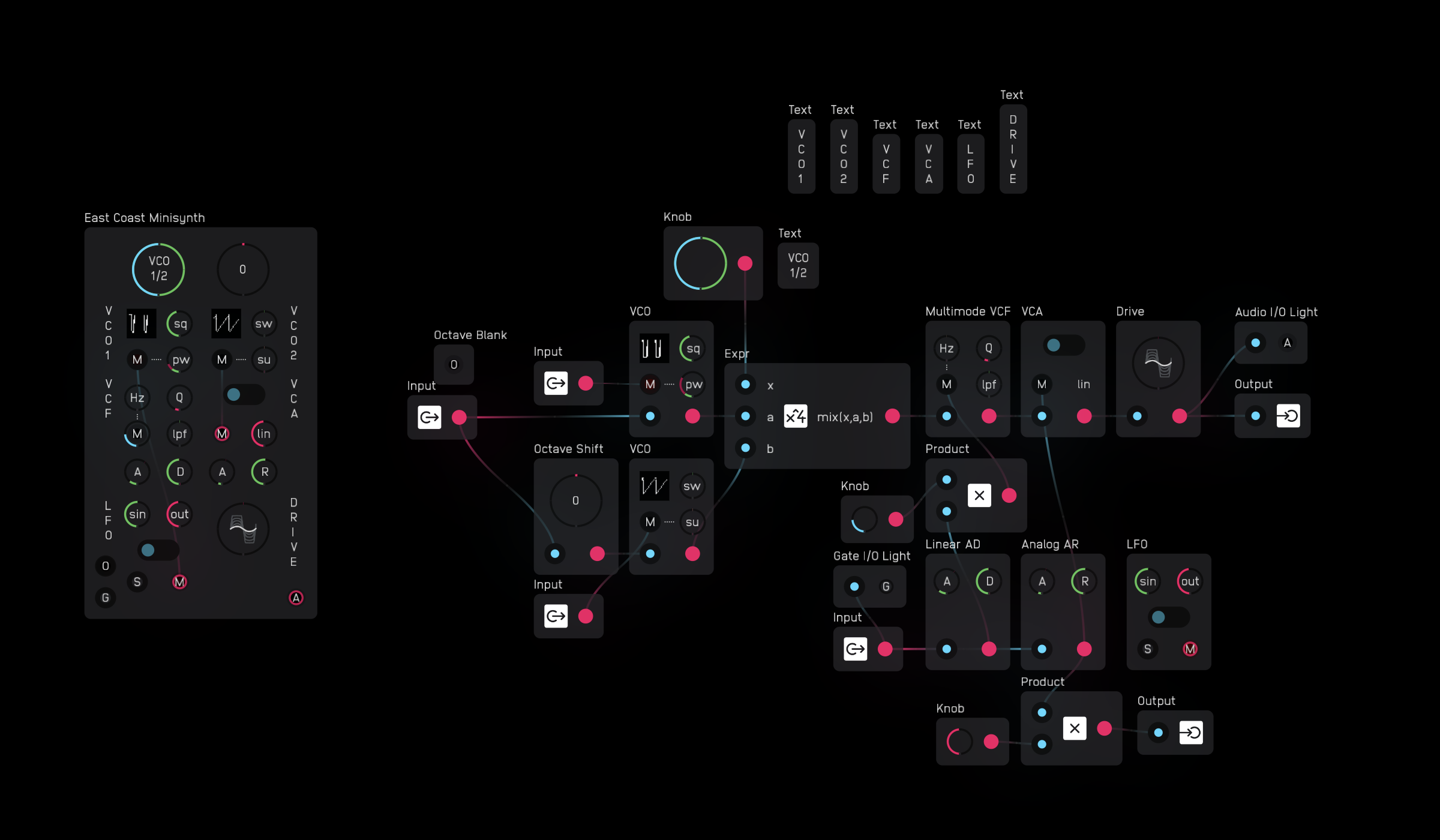
Modules
All Audulus modules are created using nodes. Each module performs a specific function to create or modify signals—some are simple, like an attenuator, while others are complex, like fully-voiced synthesizers.
To use modules effectively, you must understand the four standardized signals in Audulus: audio, gate, modulation, and octave. These signal standards ensure that modules from different creators work together seamlessly.
To download and share user-created modules, join the Audulus community forum.
Module Signal Standards
The inputs and outputs of all Audulus modules use four standardized signals. Each signal has a specific range and purpose, marked with a letter indicator for quick identification:
| Signal | Range | Indicator | Purpose |
|---|---|---|---|
| Audio | -1 to 1 | A | Sound you hear |
| Gate | 0 or 1 | G | Triggers and events |
| Modulation | 0 to 1 | M | Parameter control |
| Octave | -5 to 5 | O | Pitch information |
Audio (A)
Audio signals carry the sound your patches generate—the waveforms that become music, noise, and everything in between.
In Audulus, audio is represented as a stream of numbers between -1 and 1. This bipolar range represents the push and pull of a speaker cone: positive values push forward, negative values pull back. The back-and-forth motion creates the pressure waves you hear as sound.
Visual Indicator: Module audio inputs and outputs are marked with alternating red (positive) and blue (negative) lights. Because audio signals alternate so rapidly, the colors blend to look purple.
Important: Keep audio signals within the -1 to 1 range. Values outside this range will be clipped, causing distortion. Use a DC blocker node before audio outputs to prevent DC offset from damaging speakers.
Gate (G)
Gate signals are event triggers—the spark plugs of your patches. They tell modules when to start, stop, advance, or reset.
How Gates Work:
- Gates trigger on their rising edge—the moment they transition from 0 to any positive value
- The gate doesn't need to reach exactly 1 to trigger; any non-zero positive value works
- Gates can carry velocity information between 0 and 1, useful for dynamics
- There is no separate trigger signal in Audulus—all gates act as triggers on their rising edge
Common Uses:
- Starting and stopping envelope generators
- Advancing step sequencers
- Triggering sample & hold nodes
- Driving counters and timers
Velocity Example: When a MIDI keyboard sends a note, the gate height represents how hard you pressed the key. The adsr node responds to this velocity by scaling the envelope height, while a sample & hold node simply triggers on any rising edge above zero.
Modulation (M)
Modulation signals give your patches life—they create movement, dynamics, and evolution over time. These control signals range from 0 to 1, making them compatible with knobs and most node parameters.
Modulation Sources:
- LFOs (low-frequency oscillators)
- Envelope generators (ADSR, AR, etc.)
- Random generators
- Sequencer outputs
- Expression controllers
Modulation Targets:
- Filter cutoff frequency
- Oscillator pitch
- Effect depth (reverb, delay, chorus)
- Amplitude (volume control)
- Any knob or mod input
Control Rate vs. Audio Rate: While we typically think of modulation as "control rate" signals (slow-moving values from LFOs or envelopes), modulation in Audulus also includes audio-rate modulation:
- FM (Frequency Modulation): Audio-rate signal modulating oscillator frequency
- PM (Phase Modulation): Audio-rate signal modulating oscillator phase
- AM/RM (Amplitude/Ring Modulation): Audio-rate signal modulating amplitude
The distinction between control and audio becomes fluid—it's all just signals at different speeds.
Octave (O)
Octave signals carry pitch information using a linearized scale that makes musical math intuitive. This approach is inspired by the 1V/octave standard found in hardware modular synthesizers.
How It Works:
- Centered at 0 = reference pitch (default A440 Hz)
- Each integer represents one octave: 0 = A440, 1 = A880, -1 = A220
- Semitones are 1/12 steps: 1/12 = A♯/B♭, 2/12 = B, 3/12 = C
- Range of -5 to 5 covers most audible frequencies (13.75 Hz to 14,080 Hz)
Why Linearize Pitch? Pitch is logarithmic by nature—each octave is double the frequency. The octave signal linearizes this relationship so you can:
- Transpose easily: Add 1 for up one octave, subtract 1 for down one octave
- Scale vibrato correctly: A fixed ±0.1 vibrato sounds consistent across all octaves
- Do math musically: Adding 0.5 transposes up a tritone (6 semitones)
Without linearization, a vibrato of ±10 Hz would be dramatic in low octaves but barely noticeable in high octaves.
Module Library Categories
The Audulus module library is organized into the following categories:
- Building - Basic building blocks and utilities
- Collection - Collections of related modules
- Effect - Audio effects and processors
- Input-Output - Modules for interfacing with external devices
- Meter - Visual feedback and metering modules
- Mixer - Mixing and routing modules
- Modulation - LFOs, envelopes, and modulation sources
- Sequencer - Step sequencers and pattern generators
- Utility - Utility and helper modules
- VCA - Voltage Controlled Amplifiers
- VCF - Voltage Controlled Filters
- VCO - Voltage Controlled Oscillators
- Visual - Visual feedback and display modules
Each category contains modules designed to work together using the standard signal conventions outlined above.
Creating Your Own Modules
You can create your own modules using the module node in Audulus. Modules allow you to:
- Encapsulate complex patches into reusable components
- Create custom user interfaces with knobs, sliders, and displays
- Organize your patches into logical sections
- Share your creations with the community
To create a module:
- Select the nodes you want to include
- Group them into a module node
- Add input and output nodes to define the module's interface
- Expose controls and displays to the module's UI
- Name and describe your module
For more information on creating modules, see the Nodes Reference documentation on the module node above.
Signal Standards
Working with Signals
All inputs and outputs in Audulus are 32-bit floating point numbers. Unlike some digital modular systems, Audulus doesn't enforce signal type restrictions at a technical level—audio can be used as control, and control can be used as audio.
This flexibility is powerful, but it requires discipline. Following signal conventions ensures your modules work predictably with others and helps prevent painful accidents.
Signal Compatibility
Safe Connections:
- Audio (A) → Audio inputs
- Gate (G) → Gate or modulation inputs
- Modulation (M) → Modulation inputs, knobs
- Octave (O) → Octave inputs only
- Hz → Hz inputs only
Dangerous Connections (Avoid):
- Hz → Audio outputs: Could send thousands to a -1 to 1 range
- Octave (O) → Audio outputs: Could cause massive volume spikes
- Degrees, radians → Knobs: May cause feedback, NaN values, or painful volume jumps
What Goes Wrong: Connecting incompatible signals can cause:
- NaN/Inf values that freeze Audulus (requires restart)
- Extreme volume spikes that damage speakers or hearing
- Feedback loops that create unstable oscillations
When in doubt, check the signal range. The module library includes Translation utilities that safely convert one signal type to another.
Common Signal Types Reference
A (Audio)
Range: -1 to 1
Keep within range to prevent clipping. Use DC blocker before outputs.
G (Gate)
Range: 0 or 1 (can include velocity: 0 to 1)
Triggers on rising edge. Can carry dynamics.
M (Modulation)
Range: 0 to 1
Control signal compatible with most parameters and knobs.
O (Octave)
Range: -5 to 5 (soft limit)
Linearized pitch scale. 0 = A440 Hz. Based on 1V/octave standard.
Hz (Hertz)
Range: 0 to sampleRate/2 (Nyquist frequency)
Direct frequency control for oscillators, filters, and clocks.
k (Knob)
Range: 0 to 1
UI control signal. Often needs mapping to useful parameter ranges.
Mapping Knobs to Parameters
Knobs output 0 to 1, but parameters often need different ranges. Use the expr node's built-in functions:
Basic Mapping:
mix(knob, min, max)
Linearly interpolates between min and max based on knob position.
Exponential Response:
mix(knob*knob, min, max)
Gives more control in the lower range—useful for filter cutoff.
Logarithmic Response:
mix(sqrt(knob), min, max)
Gives more control in the upper range.
Frequency Mapping:
20*exp(knob*6.9)
Maps 0-1 to ~20 Hz-20kHz (logarithmic frequency response).
The Conversions Module
The Conversions module in the module library provides essential audio and signal conversions, handling the math safely to prevent dangerous signal mismatches:
Pitch Conversions:
- 1/Oct → Hz / Hz → 1/Oct: Convert between linearized octave scale and frequency
- Note Number → 1/Oct / 1/Oct → Note Number: Convert MIDI note numbers to pitch
- Note Number → Hz / Hz → Note Number: Direct MIDI to frequency conversion
Time Conversions:
- Hz → Seconds / Seconds → Hz: Convert between frequency and period
- Hz → BPM / BPM → Hz: Musical tempo to frequency conversion
- Seconds → Samples / Samples → Seconds: Convert time to sample count
Level Conversions:
- dB → linear / linear → dB: Convert between decibels and linear amplitude
- Unipolar → Bipolar / Bipolar → Unipolar: Convert between 0-1 and -1 to 1 ranges
Range Conversions:
- Knob → +/-3 octaves (1/oct): Map knob to ±3 octave range
- Knob → +/-12 steps (1/oct): Map knob to ±1 octave (12 semitones)
- Knob → -/+50 cents (1/oct): Map knob to fine-tuning range
These conversions are building blocks for creating modules that interface correctly with the Audulus signal standards.
Plugin Integration
The Audulus Plugin
Audulus includes a built-in AUv3 (Audio Unit version 3) plugin that works in any compatible host application. The plugin is available on all Audulus platforms: iOS, iPadOS, and macOS.
The plugin has two modes: instrument and effect.
Instrument mode receives MIDI input from a piano roll, external MIDI controller, or other MIDI source. Use instrument mode when using Audulus as a synthesizer, drum machine, or any MIDI-controlled sound source. Instruments cannot receive audio input.
Effect mode receives audio from an audio track. Use effect mode when using Audulus as an audio processor, filter, or effect. Effects cannot receive MIDI input.
Using the Plugin
The AUv3 plugin is built into Audulus and automatically available to any AUv3-compatible host application, including:
- GarageBand (iOS, iPadOS, macOS)
- Logic Pro (macOS)
- Cubasis (iOS, iPadOS)
- AUM (iOS, iPadOS)
- Beatmaker (iOS, iPadOS)
- And many other AUv3 hosts
To use the Audulus plugin:
- Open your host application
- Add an instrument or effect track
- Browse available plugins and select Audulus under the manufacturer name "Audulus"
- Choose either the instrument or effect version depending on your needs
The plugin shares the same patches as the standalone app, so you can build and test patches in standalone mode, then use them directly in your host.
Note: Audulus must be installed on your device for the plugin to function properly.